Part Number: TMS320F28379D
Hi,
I am using 28379D CMPSS module to run the peak current control by CBC trip for a synchronous buck converter. The comparator positive is from a Hall sensor output, and the comparator negative is from the internal DAC, which is a fixed number for my test.
In order to test the peak current control, I use EPWM module to generate 20 pulses and make sure the current measurement will be over the comparator threshold in my test.
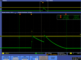
I use the scope to record the inductor current (Green), which is fed into the CMPSS comparator positive. The yellow waveform is the voltage measured from MOSFET half bridge middle point to negative bus. When it outputs high, the current (Green waveform) will increase.
To me, it seems there is a big hysteresis in the CMPSS comparator. When the current hits its peak after 2 pulses, the trip zone seems kicking in, and the PWM pulse is paused, but it waits till the current drops to half of the peak value to start the PWM pulse again. Several pulses are skipped between the second pulse and third pulse. Is it supposed to behave like this?
My PWM frequency is 50kHz and hall sensor bandwidth is 80kHz. Although its bandwidth is a little bit low, I cannot imagine it could cause this issue.
I attached my source code below.
EPwm4Regs.CMPA.bit.CMPA = 350; // duty ratio for initial condition
EPwm4Regs.TBPHS.all = 0;
EPwm4Regs.TBCTL.bit.PHSEN = TB_ENABLE; //slave mode
EPwm4Regs.TBCTL.bit.PRDLD = TB_SHADOW;
EPwm4Regs.TBCTL.bit.SYNCOSEL = TB_SYNC_IN; //sync flow-through
EPwm4Regs.TBPRD = 500; // 500*2*0.02= 20 us for up and down
EPwm4Regs.TBCTL.bit.CTRMODE = TB_COUNT_UPDOWN;
EPwm4Regs.AQCTLA.bit.CAU = AQ_SET;
EPwm4Regs.AQCTLA.bit.CAD = AQ_CLEAR;
EPwm4Regs.DBCTL.bit.OUT_MODE = DB_FULL_ENABLE; // Dead-band module
EPwm4Regs.DBCTL.bit.POLSEL = DB_ACTV_HIC; // Active High Compli
EPwm4Regs.DBFED.all = 10; // deadtime
EPwm4Regs.DBRED.all = 10; // deadtime
EPwm4Regs.CMPCTL.bit.SHDWAMODE = CC_SHADOW;
EPwm4Regs.CMPCTL.bit.SHDWBMODE = CC_SHADOW;
EPwm4Regs.CMPCTL.bit.LOADAMODE = CC_CTR_ZERO; //load on CTR = zero
EPwm4Regs.CMPCTL.bit.LOADBMODE = CC_CTR_ZERO; //load on CTR = zero
EPwm4Regs.DCTRIPSEL.bit.DCAHCOMPSEL = 3; // Take EPWM Trip 4 from Xbar
EPwm4Regs.TZDCSEL.bit.DCAEVT2 = 2; // DCAEVT2 happens when DCAH becomes high
EPwm4Regs.DCACTL.bit.EVT2FRCSYNCSEL = 1; // No sync needed
EPwm4Regs.TZSEL.bit.DCAEVT2 = 1; // Enable DCAEVT2 as CBC trip
EPwm4Regs.TZCTL.bit.TZA = 1; // Force epwm path_a to high
EPwm4Regs.TZCTL.bit.TZB = 2; // Force epwm path b to low
EPwm4Regs.DCFCTL.bit.BLANKE = 0; // Disable trip zone blank window
void InitCMPSS(void)
{
EALLOW;
//
//Enable CMPSS
//
Cmpss3Regs.COMPCTL.bit.COMPDACE = 1;
//
//NEG signal comes from DAC
//
Cmpss3Regs.COMPCTL.bit.COMPHSOURCE = NEGIN_DAC; // use DAC value
//
//Use VDDA as the reference for DAC
//
Cmpss3Regs.COMPDACCTL.bit.SELREF = REFERENCE_VDDA;
Cmpss3Regs.DACHVALS.bit.DACVAL = 950; //about 4A current
Cmpss3Regs.COMPHYSCTL.bit.COMPHYS = 0; //no hysteresis
// not use digital filter
Cmpss3Regs.COMPCTL.bit.CTRIPHSEL = CTRIP_ASYNCH;
EDIS;
}