Other Parts Discussed in Thread: TMS320F28379D, C2000WARE
- Part Number: TMS320F28379D
Dear TI,
I have a question about the nesting interrupts. I am learning this using the C2000 example because directly from my project I couldn't run my theory. The goal of this question is to confirm if a USER1 interrupt could be interrupted by another interrupt.
The USER1 interrupt is a non-maskable interrupt, which means whatever happens the CPU will reach it if a __asm(" TRAP #Number) is executed, is this interrupt could be interrupted by a higher interrupt form the other peripherals?
To make this experiment I added some small modifications to the swprioritized_interrupts_cpu01 project from c2000ware. you could do the same thing from your side if you want, for this reason I am using this example.
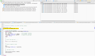
First, I added some code to the User1 ISR in this file SWPrioritizedDefaultIsr.c:
//
// Connected to USER1 of CPU (non-maskable):
//
__interrupt void USER1_ISR(void)     // User Defined trap 1
{
    EINT;

    //
    // Insert ISR Code here.......
    //
    for(i = 1; i <= 100; i++) {}


    // Next two lines for debug only to halt the processor here
    // Remove after inserting ISR Code
//   __asm ("      ESTOP0");
//    for(;;);
    //
    //  Add ISR to Trace
    //
    ISRTrace[ISRTraceIndex] = 0xCA01;
    ISRTraceIndex++;
}
The for loop is 10 times longer than the for loops in other interrupt service routines. My goal is to see if this interrupt service routine will be nested with the highest priority interrupt.
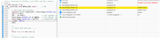
Second, I am runing the __asm(" TRAP #20") instruction after and before the PieCtrlRegs.PIEIFR1.all = ISRS_GROUP1:
//
// CASE 1:
//
#if (CASE==1)
       //
       // Force all group 1 interrupts at once by writing to the PIEIFR1
       // register
       //

       //
       // Prepare for the test:
	   // Disable interrupts
	   // Clear the trace buffer, PIE Control Register, CPU IER and IFR
       // registers
       //
	   DINT;
	   for(i = 0; i < 50; i++)
       {
           ISRTrace[i] = 0;
       }

	   ISRTraceIndex = 0;
       InitPieCtrl();

       IER = 0;
       IFR &= 0;

       //
       // Enable the PIE block
       //
       PieCtrlRegs.PIECTRL.bit.ENPIE = 1;

       //
       // Enable PIE group 1 interrupt 1-8
       //
       PieCtrlRegs.PIEIER1.all = 0x00FF;

       //
       // Make sure PIEACK for group 1 is clear (default after reset)
       //
       PieCtrlRegs.PIEACK.all = M_INT1;

       //
       // Enable CPU INT1
       //
       IER |= M_INT1;

       //
       // Force all valid interrupts for Group 1
       //
       __asm("    TRAP #20");
       PieCtrlRegs.PIEIFR1.all = ISRS_GROUP1;


       //
       // Enable global Interrupts CPU level:
       //
	   EINT;   // Enable Global interrupt INTM

       //
	   // Wait for all Group 1 interrupts to be serviced
       //
	   while(PieCtrlRegs.PIEIFR1.all != 0x0000 ){}

       //
       // Stop here and check the ISRTrace to determine which order the
       // ISR Routines completed.  The order is dependant on the priority
       // assigned in the F2837xD_SWPrioritizedIsrLevels.h file
       //
       // The ISRTrace will contain a list of values corresponding to the
       // interrupts serviced in the order they were serviced.
	   // For example if the ISRTrace looks like this
	   //        0x0014     ISR Group 1 interrupt 4
	   //        0x0017     ISR Group 1 interrupt 7
	   //        0x0016     ISR Group 1 interrupt 6
	   //        0x0015     ISR Group 1 interrupt 5
	   //        0x0018     ISR Group 1 interrupt 8
	   //        0x0012     ISR Group 1 interrupt 2
	   //        0x0011     ISR Group 1 interrupt 1
	   //        0x0000     end of trace
       //
	  __asm("        ESTOP0");
I am executing the first case of the example.
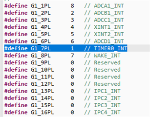
I am using the same F2837xD_SWPrioritizedIsrLevels.h from TI:
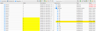
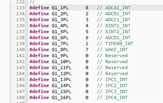
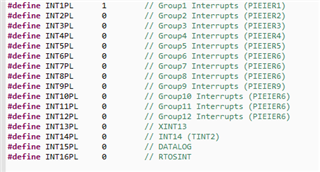
#define	INT1PL      2        // Group1 Interrupts (PIEIER1)
#define	INT2PL      1        // Group2 Interrupts (PIEIER2)
#define	INT3PL      4        // Group3 Interrupts (PIEIER3)
#define	INT4PL      2        // Group4 Interrupts (PIEIER4)
#define	INT5PL      2        // Group5 Interrupts (PIEIER5)
#define	INT6PL      3        // Group6 Interrupts (PIEIER6)
#define	INT7PL      5        // Group7 Interrupts (PIEIER6)
#define	INT8PL      5        // Group8 Interrupts (PIEIER6)
#define	INT9PL      3        // Group9 Interrupts (PIEIER9)
#define	INT10PL     6        // Group10 Interrupts (PIEIER6)
#define	INT11PL     6        // Group11 Interrupts (PIEIER6)
#define	INT12PL     8        // Group12 Interrupts (PIEIER6)
#define	INT13PL     4        // XINT13
#define	INT14PL     4        // INT14 (TINT2)
#define	INT15PL     4        // DATALOG
#define	INT16PL     4        // RTOSINT


...
#define G1_1PL		5		// ADCA1_INT
#define G1_2PL		3		// ADCB1_INT
#define G1_3PL		1		// ADCC1_INT
#define G1_4PL		4		// XINT1_INT
#define G1_5PL		4		// XINT2_INT
#define G1_6PL		1		// ADCD1_INT
#define G1_7PL		12		// TIMER0_INT
#define G1_8PL		5		// WAKE_INT
#define G1_9PL		0   	// Reserved
#define G1_10PL		0   	// Reserved
#define G1_11PL		0   	// Reserved
#define G1_12PL		0   	// Reserved
#define G1_13PL		8		// IPC1_INT
#define G1_14PL		13		// IPC2_INT
#define G1_15PL		15		// IPC3_INT
#define G1_16PL		9		// IPC4_INT
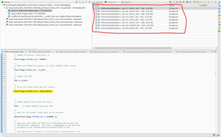
Results:
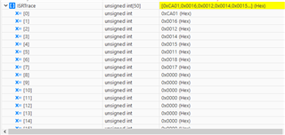
In this picture, we could see that the USER1 interrupt gets the first interrupt executed even if #define G1_3PL 1 // ADCC1_INT is the highest priority?
Does the USER interrupt is interrupted when the ADCC1_INT it has arrived? I am not sure that the USER1 interrupt is nested with th high priority, I think that even if we define the highest priority interrupts, when USER interrupt start execution it doesn't stop till the end and other highest priority are in the pending state.
Could you please clarify this point?
Thank you in advance,
Regards,
S.Tarik