This thread has been locked.

If you have a related question, please click the "Ask a related question" button in the top right corner. The newly created question will be automatically linked to this question.

TMS320F28377D: DCL Controller function outputting negative values even with positive error input

Part Number: TMS320F28377D
Other Parts Discussed in Thread: C2000WARE, SFRA

Hi,

Bit of a confusing one, but I was wondering why a digital control library function such as that to run a 2P2Z controller might output a negative value, especially if the error input is positive. 

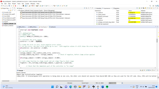
I have tried changing the coefficients many times and still I will often get a significant negative voltage returned after calling the function, rendering the controller pretty much useless. Here is a screenshot:

Even with zero volts input to the ADC pin that measures the voltage for the error calculation, the function can very often return negative float values. Is this just a coefficient issue?

If I place a very small gain, KDC (I am using the C2000Ware compensation designer), the voltage output can be positive, but very small. Then, as I increase the KDC gain, there comes a point where the output from the function returns negative. It is very frustrating as you would think increasing the gain would just increase the controller output, not make it negative. 

I have wrote this code essentially from a DCL library example and did the exact same functions.

Can anyone suggest a reason why this might be happening, and a possible fix? 

EDIT: I noticed in the DCL Users Guide, the following: 

Step 3. Allocate the controller functions in the linker command file DCL functions which run on the FPU32 or C28x core can be allocated to a specific memory block in the linker command file. It is common to place the controller functions in zero wait-state internal RAM since this allows them to run at the maximum speed of the device. Note that all CLA functions must run from internal zero wait-state RAM. All DCL library functions are placed in the user defined code section .dclfuncs. An example showing how this section might be mapped into the internal L4 RAM memory block is shown below. dclfuncs : > RAML4, PAGE = 0 See also the linker command file F28069_DCL.cmd in the project examples (chapter 5). In a stand-alone application, code must be stored in non-volatile memory (such as internal flash) and copied into RAM at run-time. For information on how to do this, refer to the Using the Digital Control Library 20 application note “Running an Application from Internal Flash Memory on the TMS320F28xxx DSP”, TI literature number SPRA958. Information on linker section allocation can be found in the “TMS320C28x Assembly Language Tools User’s Guide”. 

I am not sure if I have done this - if I haven't done the above step, would the controller code even run at all? 
If the code was able to run without the above, could it cause significant issues with the results of the controller output?
It seems to be running OK - but I am not sure how fast it is executing and how accurate the controller output results I am being showed are: it would be a great help if someone was able to email me the F28069_DCL.cmd file to my email: j.holland3@newcastle.ac.uk - as I am still having the issue that the C2000Ware folders do not have any project properties and none of them include command files, either. I think this could solve my problem.

Best regards,

Joel

  • I realised I was using the partial controller results for this code. I changed it to use DF22_L1 which is the full controller implementation. But even with very small coefficeints my controller now bounces around from +inf to -inf, switching between maximum and minimum duty:

    Any suggestions at all are welcomed, not sure at all what is happening here.

  • Joel,

    Just a heads up that today the 30th is a US Holiday, you should expect a technical reply from one of our engineers by tomorrow US time.

    Best,

    Matthew

  • Hi Matthew, 

    Just putting my code here for the DCL/CLA code to see if anybody can spot an issue with the code. 

    #include "DCLCLA.h"
    #include "F2837xD_Cla_typedefs.h"
    #include <stdbool.h>
    #include "F2837xD_Cla_defines.h"
    #include "F28x_Project.h"
    
    // Digital Control Library Structures
    DCL_DF22_CLA v_ctrl2;              // Pre-computation controller structure definition for voltage compensation
    DCL_DF11_CLA i_ctrl2;              // Pre-computation controller structure definition for current compensation
    
    float32_t flagVolts, flagCurr;         // Clamp flag variables
    float32_t i_upperLim, i_lowerLim;      // Upper clamp limit of digital compensation block
    float32_t v_upperLim, v_lowerLim;      // Lower clamp limit of digital compensation block
    
    // Sensor data that is passed from the CLA to CPU must be declared as external (shared memory)
    //extern uint16_t inputVolts;
    extern float32_t flyVolts, flyCurr;
    extern float32_t cathodeRef;            // Soft-started from CPU1 ISR background loop
    extern float32_t flyback_command;
    float32_t clamp_switch;                  // Clamp switch is not communicated to CPU1 so does not need external declaration
    float32_t voltage_command;               // Fly-back command only needs to be defined as shared variable in CPU1
    float32_t voltageCommand_partialResult;
    float32_t voltage_command_neg_check;
    float32_t flyback_command_neg_check;
    
    float32_t controllerDifference;
    
    // Feedback the HRPWM calculations to CPU1
    extern uint32_t compCount_clamp;
    extern uint32_t compCount_flyback;
    
    // Error values
    float32_t voltError, currError;
    
    // CLA1 C Task Prototypes
    __interrupt void Cla1Task1();
    __interrupt void Cla1Task2();
    __interrupt void Cla1Task3();
    __interrupt void Cla1Task4();
    __interrupt void Cla1Task5();
    __interrupt void Cla1Task6();
    __interrupt void Cla1Task7();
    __interrupt void Cla1Task8();
    
    interrupt void Cla1Task1 (void)
    {
    
    // 100MHz/100 = 1MHz.
    uint32_t HRPWM_FLY_PERIOD_CLA = 100UL;
    
    // Calculate the error signal
    voltError = 1.338f - flyVolts;
    
    // Clamp the error to zero, avoid negative error values
    // At zero error, the duty cycle should go to zero - with negative values it still shows the error being 3.0f.
    if(voltError < 0) voltError = 0.000f;
    
    // run full controller, L1. L2 is partial controller.
    voltage_command = DCL_runDF22_L1(&v_ctrl2, voltError);
    voltage_command_neg_check = voltage_command;       // Check if negative, before clamp action applied
    
    voltageCommand_partialResult = DCL_runDF22_L2(&v_ctrl2, voltError);
    
    // Call clamp function to clamp result and set clamp flag to check range
    flagVolts = DCL_runClamp_L1(&voltage_command, v_upperLim, v_lowerLim);
    
            // Check that the immediate part of the controller is "in range"
            if (0.0f == flagVolts)
            {
                DCL_runDF22_L3(&v_ctrl2, voltError, voltage_command);
            }
    
            controllerDifference = voltage_command - voltageCommand_partialResult;
    
             if(voltage_command < 0.000f) voltage_command = 0.000f;
    
            // Clamp maximum and minimum average current command to inner current loop
            voltage_command = (voltage_command > v_upperLim)?
                                    v_upperLim:voltage_command;
            voltage_command = (voltage_command < v_lowerLim)?
                                    v_lowerLim:voltage_command;
    
    // Calculate the average current error using the previous compensated voltage error as target reference
    // DCL library uses floats, but flyCurr is an int, so type-cast
    currError = voltage_command - flyCurr;
    
    // Run partial DF11 Controller and clamp function
    flyback_command = DCL_runDF11_L1(&i_ctrl2, currError);
    flyback_command_neg_check = flyback_command; // Before clamping, let's see if negative output value
    
            // Clamp maximum and minimum duty cycles
            // sets to between 0.1 and 0.35
            flyback_command = (flyback_command > i_upperLim)?
                                    i_upperLim:flyback_command;
            flyback_command = (flyback_command < i_lowerLim)?
                                    i_lowerLim:flyback_command;
    
            clamp_switch = (1 - flyback_command);
    
            // HRPWM Calculations
            float32_t count_clamp = (flyback_command * (float32_t)(HRPWM_FLY_PERIOD_CLA/2 << 8));
                            compCount_clamp = (count_clamp);
                            uint32_t hrCompCount_clamp = (compCount_clamp & (0x000000FF));
                            if (hrCompCount_clamp == 0)
                            {
                                // Add 1 to not have CMPxHR = 0
                                compCount_clamp |= 0x00000001;
                            }
    
            float32_t count_flyback = (clamp_switch * (float32_t)(HRPWM_FLY_PERIOD_CLA/2 << 8));
                            compCount_flyback = (count_flyback);
                            uint32_t hrCompCount_flyback = (compCount_flyback & (0x000000FF));
                            if (hrCompCount_flyback == 0)
                            {
                            // Add 1 to not have CMPxHR = 0
                            compCount_flyback |= 0x00000001;
                            }
    }
    
    __interrupt void Cla1Task2 ( void ) {}
    
    __interrupt void Cla1Task3 ( void ) {}
    
    __interrupt void Cla1Task4 ( void ) {}
    
    __interrupt void Cla1Task5 ( void ) {}
    
    _interrupt void Cla1Task6 ( void ) {}
    
    __interrupt void Cla1Task7 ( void ) {}
    
    //Task 8 will initialize the variables used in Task 3
    __interrupt void Cla1Task8 ( void ) {
    //  __mdebugstop();
    
        // Initialise DF22 Full Voltage Controller Compensation Coefficients
        // Use the GUI in POWERSUITE for Digital Compensation for easy coefficient calculations according to the poles and zeroes in HZ
        v_ctrl2.a1 = 1.1201983f;
        v_ctrl2.a2 = -0.1201983f;
        v_ctrl2.b0 = 0.0798453f;
        v_ctrl2.b1 = -0.1482259f;
        v_ctrl2.b2 = 0.0686588f;
    
        // Initialise DF11 Full Current Controller Compensation Coefficients
        i_ctrl2.a1 = 0.21606f;
        i_ctrl2.b0 = 0.22090f;
        i_ctrl2.b1 = 0.31307f;
    
        // clamp limits of both the voltage and current controllers
        v_upperLim = 100.000f;    //3.000f replaced, just for voltage mode control for now    // 3A (3V) average current limitation
        v_lowerLim = -100.000f;
        i_upperLim = 0.850000f;       // 35% duty cycle limitation maximum
        i_lowerLim = 0.1500f;         // 0% minimum duty cycle limitation
        flyback_command = 0.0f;       // Initialise fly-back command
        voltage_command = 0.0f;       // Initialise average current reference command
        voltageCommand_partialResult = 0.0f;
        controllerDifference = 0.0f;
    
        voltError = 0.0f;             // Initialise voltage and current errors
        currError = 0.0f;
    
        voltage_command_neg_check = 0.000f;
        flyback_command_neg_check = 0.000f;
    
    }
    

  • Hi Joel,

    Thanks for sharing the code. I see you are calling L1, L2 and L3 of the DF22 function in the same CLA task for the same compensator (v_ctrl2). This is not what we designed these functions for. You should either use L1/L4 by itself or use L2 + L3. Unless you have a specific reason to separate the compensator (saturation or early update of control signal), it will be easier to use L1/L4 for the compensator.

    One suggestion I have to eliminate potential error on your setting on CMD file or other place is to use the L4, which is implemented in C, and should not be affected by any other settings.

    Regarding the compensator coefficient, have you tried to simulate the compensator coefficient with simulation software like MATLAB Simulink? You can make sure it works fine in simulation before trying it on hardware. We have a compensator designer tool (under the SFRA folder in library of C2000 digital power SDK https://www.ti.com/tool/C2000WARE-DIGITALPOWER-SDK) that will have you generate the compensator coefficient based on your desired gain and pole / zero location.

    Best regards,

    Han

  • Hi  . I now have tried to just use the L4 alone, so no assembly, and still I have issues. The output from the controller is all over the place.

    I have stumbled across what is causing the issue, but I have no clue why or how to resolve it. 

    Instead of calculating the error voltage by taking the reference and subtracting the flyback output voltage:

    voltage_error = cathodeRef - flyVolts;

    Here is a graph from the debugger, which as you can see is all over the place:

    I instead initialize the code with a fixed error voltage that does not use the ADC samples:

    voltage_error = 3.0f;

    Here is a graph from the debugger for this version:

    The controller output is fixed at about 0.01823!

    And the controller seems to have a nice, constant and fixed output. When I use the first code, the output voltage is completely erratic, and almost oscillates, even if the ADC voltage sensor is given zero volts. 

    What may be causing this behaviour? Is there possibly something wrong with how I initialize memory shared between the CPU1 and CLA1? I'm not sure if this is the case, because in the debugger we can see that the flyVolts and the error_voltage is calculating correctly. These very, very small float value variations in the cathode ADC value reading causes the controller to be completely unstable, but it is completely stable if we take that out of the equation!

    Any advice for where to go from here?

    Best,
    Joel

  • Hi Joel,

    It is less likely to be a setting issue. You may need to refine your compensator design (especially if you have not verified it). We do have the Simulink model of the DCL blocks (including DF22) in the models folder of the DCL library release.

    If you still have concern, you may try to collect the voltage_error from CLA and plot it on a graph. This way you can verify if your feedback value is the issue.

    You can also verify the calculation of the compensator in CLA by collecting your feedback and control output in RAM, export them to PC and verify the calculation result on the PC.

    I did not see what your feedback signal looks like, but if your compensator is too aggressive and made the output voltage oscillate quickly, the control signal seems to look reasonable.

  • I have already used the C2000 DF22 calculator and have got my coefficients equal to those I would expect to place the poles and zeros at my selected frequencies. I will try MATLAB etc tomorrow. 

    What happens if the optimal gain value for the controller causes the output of the controller to be below the minimum duty cycle that is required? Is it acceptable to “scale” the controller output by some scale value? Will multiplying the controller output by an additional gain cause the controller to be incorrect? I know you can increase the gain of the actual controller by increasing the B coefficient values of the controller, but this seems to be what causes instability in the controller output. 

    would scaling the actual controller output by an additional factor cause issues with instability? 

    for clarity, my flyVolts can be 0.0001, causing my error voltage to chance from 3.0000 to 2.9999, and still that erratic controller response from 0-15% duty cycle is observed. 

  • Hi Joel,

    Actually “scaling the output” will be equivalent to change compensator gain. Hence everything that could happen when you bump up your controller coefficient will happen if you scale the output in the same way. Again, you can actually verify the effect of output scale in simulation first and see the effect before running hardware test if you wish.

    Han

  • Hi Han,

    After looking again through the DCL user guide, it seems like I have not been resetting the DCL delay lines before executing and debugging the code. The user guide states that the delay lines have to be initialized to zero in the main code to avoid wrong results.

    However, there is no function to achieve reset of the controller delay lines for a DF22 controller... the only functions are void DCL_resetDF22(DCL_DF22 *p), held in DCLF32.h. The argument is for DCL_DF22 and there is no reset function that allows DCL_DF22_CLA as an input. Why is this? How does one set the delay lines to zero when implementing a CLA controller? Is there some mechanism that allows the controller to be set to zero without executing this code?

    Best regards...
    Joel

  • Hi Joel,

    If you are trying to do a initial reset of the delay line (before enable the CLA task), you can just set x1 and x2 from the DCL_DF22_CLA struct on the CPU, since CPU have full access to CLA data RAM. If you want to do it on the go after enable the CLA task, you may consider disable CLA task before reset the two registers, and reenable it afterwards. Hope this will answer your questions. Thanks.

    Han

  • Hi Han,

    I saw in another example of a DF23 CLA code that the X1, X2, and X3 delay lines can be set to 0.0f in the CLA initialization task in the same manner the coefficeints are set. In the CLA, I added the following to the existing init code;

    // Start off with 0dB = 1.0f Gain.
    v_ctrl2.a1 = 1.0062300f;
    v_ctrl2.a2 = 0.0444510f;
    v_ctrl2.a3 = -0.0506810f;
    v_ctrl2.b0 = 2.5101066f;
    v_ctrl2.b1 = -6.7263321f;
    v_ctrl2.b2 = 6.0075406f;
    v_ctrl2.b3 = -1.7883328f;
    v_ctrl2.x1 = 0.0f;
    v_ctrl2.x2 = 0.0f;
    v_ctrl2.x3 = 0.0f;

    And I can see a little bit more of what is going on now with the controller. For example, at full error: 

    And then, at close to zero error: 

    Despite the X1, X2, and X3 values clearly showing a significant decrease, the u1k and u2k values are still all over the place. Not sure if that indicates any issue.

    For the C2000Ware digital compensator designer, do you HAVE to model the converter that is to be controlled? Are the digital compensator coefficients dependent at all on the model of the converter that is to be controlled?

    It is my understanding that if I know exactly where my poles need to be, due to me calculating where they need to be from the output capacitors, inductors, ESR's and control frequency etc - I can just set those frequencies in the digital compensator designer and copy and paste the output coefficients without having to worry about the plant that I am compensating. Is this wrong? If I was to actually model my buck converter in the SFRA, would this cause a significant change in the digital controller coefficients even if the pole and zeroes location was to stay the same?

    Best,
    Joel

  • Hi Joel,

    You can sure use the compensator designer in both ways. If you know where you want your zero, pole and gain to be, you can use it as a tool for calculation the compensator coefficient only. Please make sure the sampling frequency you put in the designer matches your sampling / CLA task frequency.

    If you use SFRA to get frequency response of the power stage, you will be able to get interactive view of the open loop / closed loop frequency response while designing the compensator, which will help you make decision for the design. This similar to the SISOtool offered by Mathworks.

    BTW, I did a quick simulation of the DF23 parameter you showed. I am not sure the sampling frequency you have, but it looks like it is 1Msps based on earlier discussion. I did get a response that will oscillate for a couple of rounds before it get into a constant. Please see figure below. I set a 1.0 constant error in the simulation. Thanks.

    Han

  • Hi Han,

    Thank you for a very informative response. I thought that the frequency input to the designer was the sewitching frequency rather than the sampling frequency. I sample at 400kHz, average the signals and then launch the CLA at 70khZ which is the loop bandwidth / crossover frequency of the converter - which frequency would you choose in this case for the designer input? If it is not the switching frequency, is it the sampling frequency or the ISR frequency - because they are not always the same! The poles frequencies would then be much higher than the sampling frequency / frequency used for the designer, because we usually place them in the region of half the switching frequency (500kHz) and higher.

    from the MATLAB figure you have given you would think that the controller was indeed stable after some time. As I said I have kept 0V on my ADC inputs such that the error should be very close to being constant other than some remnant measurement or offset. Would you be so kind as to send the MATLAB file such that I can see how you are simulating the digital controller? 

    best regards and have a great weekend. 
    Joel

  • Hi Joel,

    It seems you have 3 frequency in your system: switching, sampling and control (CLA) update frequency. The easiest way (ideal) is to keep all 3 frequency the same. This will avoid confusion in your design. If you have to have different value, them the one used for compensator design should be the control update (CLA) frequency.

    If your compensator is complicated and take high cycle count or you have a VERY fast switching frequency (say 1MHz), you can also make the sample / control frequency to be integer fraction of the switching frequency (unless you have a variable frequency topology like LLC). If you only have a DF22 compensator, we have no pressure to run the compensator at 400 kHz sampling frequency.

    Based on digital control theory, your sampling frequency will need to be 10-20x your loop bandwidth (crossover frequency) to keep the system stable. Your system will not be stable if you have 70k bandwidth and only 70 kHz control frequency. Please make sure to verify your system design (including how you sample, average, control, update) in simulation to make sure your system is stable.

    Han

  • Hi Han, 

    I have some strong confusion with the above statement. The control bandwidth of a converter is the band of frequencies where the system can respond satisfactorily. If your controller has a bandwidth of 83kHz, why would you launch the controller at any frequency higher than this, if the system cannot respond faster than that? The output from the digital controller/compensator would not be useful in that instance. 

    Therefore, it makes sense that the maximum "control frequency", is limited by the controller "bandwidth". It does not make sense why you cannot launch the compensator at, or just below the maximum bandwidth, and it certainly seems to make more sense than launching it any faster than that, as you suggest?

    Can you clarify?

    Best regards,

    Joel

  • Hi Joel,

    In digital control, the ADC sampling --> Compensator calculation --> PWM output process will introduce delay of ~ 1.5x sampling time, which will cause phase lag and cause system to run unstable if the system bandwidth is too high (close to sampling frequency). In classic control theory, it is recommended to have the sampling frequency > 20x control bandwidth.

    Please be aware that E2E is mainly used to support customers debugging issues or coming across unexpected errors in their device. We have limited bandwidth in these support and will not be able to go deep into control theory. You may want to refer to some classic control / digital control text books, or do some more simulation in software such as MATLAB Simulink on the discrete controller you designed, before testing them in real hardware implementation. This will help you decouple design errors and issue with C2000 implementation. Thanks.

    Best regards,

    Han