This thread has been locked.

If you have a related question, please click the "Ask a related question" button in the top right corner. The newly created question will be automatically linked to this question.

TIDA-02007 and DRV8316 Firmware Question

Other Parts Discussed in Thread: TIDM-02007, DRV8316, DRV8316REVM, INSTASPIN-BLDC, C2000WARE-MOTORCONTROL-SDK, C2000WARE

Hi Team,

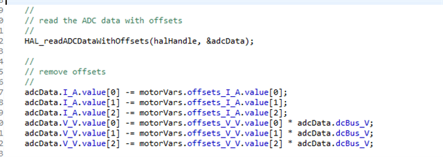
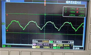
My client is now using the TIDM-02007 based code and switching the driver to a DRV8316. This means that the way current sampling is changed, from in-line current sampling to low-side sampling. In the TIDM-02007 code, we use the SINGLE_SAMPLING mode, which is the PWM triggering the ADC for sampling.

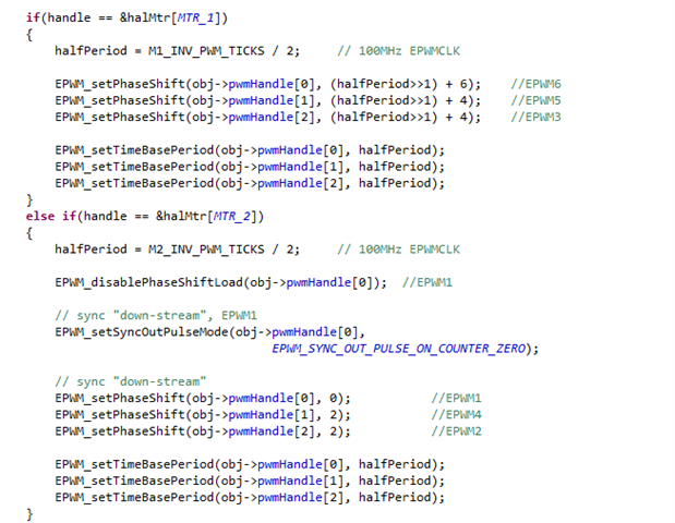
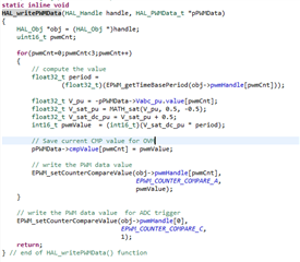
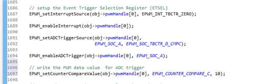
I also checked the reference code "drv8316revm" for DRV8316+280049(3782.drv8316revm.zip), can I know when the ADC is sampling for this code? (PWM rising edge? Or at PWM center? Where is that stated?) If I switch from TIDM-02007 in-line current sampling code to DRV8316's low-side current sampling, does my ADC sampling need to change(Do I need to change current loop)? 

Thanks

Jenson

  • can I know when the ADC is sampling for this code? (PWM rising edge? Or at PWM center? Where is that stated?) If I switch from TIDM-02007 in-line current sampling code to DRV8316's low-side current sampling,

    Trigger ADC at all of the three low-side are ON and the three high-side are OFF when the PWM counter equals to zero.

    oes my ADC sampling need to change(Do I need to change current loop)? 

    Not need to change anything if using the SINGLE SAMPLING MODE, and only this mode supports low-side shunt current sensing.

  • Hi Yanming,

    Thanks for your kindly help! I have another question about this topic

    1. For ow-side current sampling, getting the current value at high duty cycle becomes difficult, I looked at the code for the DRV8316 and I don't seem to find a way to use the calculation to get the three phase current at high duty cycle Function.3782.drv8316revm.zip Do we have such a function in the code of DRV8316?I convert (TIDM-02007) in-line samples to low-side samples (DRV8316), can I not add this function?

    2.I checked the polarity of the hardware ADCs of the two designs, and I think I don't need to change the polarity of the ADC, right? Do you think there is anything to be aware of in converting the code from the in-line samples of the TIDM-02007 (using SINGLE_SAMPLING Mode) to the low-side sampling of the DRV8316? Or can I just go and use (with the correct gain set)

    Thanks again

    Jenson

  • Hi Yanming,

    I encountered another problem when modifying the code, Could you kindly give me a hand ? We are working on an urgent project and really need your help. Thanks in advance!

    I need to change the PWM Motor1 channel of TIDM-02007 to EPWM1_BASE, EPWM2_BASE, EPWM3_BASE (original is EPWM6,5,3), and I need to disable motor2

    1. For I modified the channel, do I need to modify the phaseshift of the EPWM?


    2. I found that after I modified the channel of EPWM, the interrupt could not be triggered (isrTicker has no digital increase), but I have set the interrupt source to INT_EPWM1, you cannot enter the interrupt. Do you have any comments?

    Thanks!

    Jenson

  • If you just want to run a single motor with DRV8316, you may refer to the Universal Motor Control Lab as below

    You may download and install the latest MotorControlSDK,  which can support a set of hardware kits and control algorithms for BLDC/PMSM drive. The kits include LAUNCHXL-F280025C with BOOSTXL-DRV8323RS, or BOOSTXL-DRV8323RH, or DRV8353Rx-EVM, or BOOSTXL-3PHGANINV, or DRV8316REVM. The control algorithms include InstaSPIN or eSMO based Sensorless-FOC, and incremental encoder or hall sensor based sensored-FOC,and sensorless trapezoidal BLDC control with InstaSPIN-BLDC. The detailed introduction about the lab can be found in the lab user’s guide as the links below.

    C2000WARE-MOTORCONTROL-SDK: https://www.ti.com/tool/C2000WARE-MOTORCONTROL-SDK

    Universal Project and Lab User’s Guide: https://www.ti.com/lit/spruj26

    Example lab project at the folder: C:\ti\c2000\C2000Ware_MotorControl_SDK_<version>\solutions\universal_motorcontrol_lab\f28002x

    If you want to run the TIDM-2007 with DRV8316, you need to change the PWM, ADC and CMPSS configuration codes for current&voltage sensing and protection in "dual_axis_servo_drive_hal.c" , "dual_axis_servo_drive_hal.h", and "dual_axis_servo_drive_user.h" according to the DRV8316 board.

    1. For I modified the channel, do I need to modify the phaseshift of the EPWM?

    If you just run a signal motor, just need to set the phase shift as below.

      EPWM_setPhaseShift(obj->pwmHandle[0], 0); //EPWM1
      EPWM_setPhaseShift(obj->pwmHandle[1], 2); //EPWM2
      EPWM_setPhaseShift(obj->pwmHandle[2], 4); //EPWM3 

    2. I found that after I modified the channel of EPWM, the interrupt could not be triggered (isrTicker has no digital increase), but I have set the interrupt source to INT_EPWM1, you cannot enter the interrupt. Do you have any comments?

    Change the PWM assignment to motor, don't assign the same PWM module to both motor

    #define M2_U_PWM_BASE EPWM1_BASE // NC: Set up based board
    #define M2_V_PWM_BASE EPWM4_BASE // NC: Set up based board
    #define M2_W_PWM_BASE EPWM2_BASE // NC: Set up based board

    #define M2_INT_PWM             INT_EPWM1           // NC: Set up based board

  • Hi Yanming

    Thanks for your kindly help! It's very helpful ! I have another question about this topic

    1. For ow-side current sampling, getting the current value at high duty cycle becomes difficult, I looked at the code for the DRV8316 and I don't seem to find a way to use the calculation to get the three phase current at high duty cycle Function.3782.drv8316revm.zip Do we have such a function in the code of DRV8316?I convert (TIDM-02007) in-line samples to low-side samples (DRV8316), can I not add this function?

    2.I checked the polarity of the hardware ADCs of the two designs, and I think I don't need to change the polarity of the ADC, right? Do you think there is anything to be aware of in converting the code from the in-line samples of the TIDM-02007 (using SINGLE_SAMPLING Mode) to the low-side sampling of the DRV8316? Or can I just go and use (with the correct gain set)

    Thanks again

    Jenson

  • No such functions for this in TIDM-2007, you have to limit the duty cycle. Not recommend to use DRV8316 for FCL since it's difficult to get a high accuracy current sensing signal in all of the load and temperature range.

    You need to change the sign of the current scale factor in "dual_axis_servo_drive_user.c" to meet the current sensing circuit in the DRV8316 as below.

            pMotor->FCL_params.adcScale = M1_ADC_PU_PPB_SCALE_FACTOR;

  • Hi Yanming,

    Thanks for your kindly reply.

    And I would like to know if in DRV8316 EVM have such function for calculate the phase current in high duty cycle(in DRV8316evm ref code 3782.drv8316revm.zip?  if drv8316 evm reference code also limit the duty cycle here or there are other  method to realize it?

    Thanks!

    Jenson

  • DRV83126 use the RS of low-side MOSFET to estimate the phase current that is similar to use the shunt resistor on low-side, but the RS of low-side MOSFET will be variable with the temperature of the FET.

    The duty limit is based on the FCL algorithm and low-side current sampling mode.

  • Thanks!

    Actually, I looked at the code for the DRV8316 and I don't see a duty that limits the PWM in HAL_wirtePWM. For the DRV8316, is it limiting the output in the current loop PID?

    Thanks

    Jenson

  • Yes, the maximum modulation index (duty) is limited in the current PI controllers.

  • Hi Yanming,

    Thanks for your reply.

    I tried to use the code of TIDM-02007 to drive the DRV8316, I found that I can't run the motor in LEVEL3. When I set the iq value, the motor seems to be stalled, and I checked the current sampling, and I didn't get a valid current value, but there is actually a lot of current. So I want to double check, is this code suitable for low-side sampling? or what kind of comments you have, please let me know!

    BTW, the customer wants to use DRV8316+280049+sin/cos sensor. Do we have a more suitable code than TID-02007 to modify to suit the needs of customers?

    Thank you very much for kindly help again!

    Jenson

  • Run the motor in LEVEL 2 first, to verify if the current sensing and position feedback signals are correct. You may try to use the on-chip DAC to check the sensing current. If the current sensing signals are not correct, you have to check the DRV8316 configuration.

    The user has to refer to the existing reference code like TIDM-02007 and migrate the project according to their hardware by themself.

  • Hi Yanming,

    Thanks for your continued help. I'm currently having another problem


    1. Since I changed the interface of ADC, I need to reset the interface of CMPSS
    I checked TIDM-02007, for MOTOR1, B2, C0, A9 are used. I checked CMPSS using CMPSS3. But only B3 has a corresponding CMPSS3 channel, and C0, A9 correspond to CMPSS1, CMPSS6 respectively. What is this? Woolen cloth? Why can I use CMPSS3 in three channels of B2, C0 and A9?


    2. I am currently using A0, A1, A2, how should I set CMPSS accordingly?

    Thanks again!

    Jenson

  • That's limited to CMPSS number on device or the ADC pins assignment on LaunchPad, so only one or two phase current is protected by CMPSS on F28002x or F28004x. Ideally, the user should assign the right ADC channel supporting CMPSS to the each phase current sensing.

    Just need to change the ADC base address, SOC number, channel number, and CMPSS base address in the header file according to their own hardware board.

  • Hi Yanming,

    First of all, I would like to thank you for your support. We can successfully run the code ported from TIDM-02007 on the customer side and use it on 280049+DRV8316.

    But there are still some small problems in the operation of our code, I want to discuss with you.

    1. Current Loop waveform slight change in amplitude

    When we run the motor at a frequency of 10KHz, the waveform of the current loop is good, but the current waveform will oscillate slightly at >50RPM, and the waveform will be large and small. (Looks like the current loop isn't tuned well), what are your comments on this? Do we need to change the current loop parameters?(Customer's speed range is 0~60RPM)

    2.Changing the PWM frequency leads to distortion of the current waveform

    Since we can hear noise at 10KHz, we try to set the PWM frequency to 20HZ, and we find that the current waveform has serious distortion, which is more obvious when the speed is fast, and the current loop is very unstable. The figure shows the current distortion at low speed.
    I think it may be caused by ADC sampling, because the faster the frequency, the shorter the ADC sampling window. Below is how my ADC triggers code. Do you have any comments on this? Or what else do you think could be causing this factor? (I have tested that after 12KHz, the current gradually starts to distort from high speed (about 50PRM), and after 20KHz, the current starts to distort from about 10RPM) (Our code is a reference to the TIDM-02007 implementation)

    Appreciate you support again!

    Thanks!

    Jenson

  • 1. Yes, you need to tune the gains of both speed and current PI controller. Even, you should use different gains for low and high speed.

    2. You need to change the limitation modulation index according to the PWM frequency, and ensure there is enough sample time for current sensing, and no wrong PWM update.

  • Hi Yanming,

    Sorry to bother you again,

    First of all thanks for your help. I also wonder if we at TI have code for low side sampling at high duty cycle(high load)?


    I looked at the code for the DRV8316, and it's all processed through the two-phase current. I understand that under high load, it should be judged whether the duty of a certain phase is too large, so the current of the other two phases is collected. Do we have this reference code?

    Thanks again.

    Jenson

  • No reference code for this FCL lab. There is an example code in the other FOC reference, but it's not suitable to use in FCL lab since the current re-construction will take much more CPU cycles. The FCL lab is better to use the inline shunt current sensor or hall sensor.

    You can find the over-modulation and current re-construction code in the InstaSPIN-FOC example labs.

  • Hi Yanming,

    Thanks for your help. It's very helpful!

    For the parameter setting of the current loop, what is the difference between FCL and universal?


    I see the general situation is as follows:


    But FCL is like this. What is the principle of operation in FCL?

    What does the calculation of invZbase mean?

    Thanks!

    Jenson

  • Yanming is currently out of the office, please expect our next reply by this Friday the 15th.

    Best,

    Matthew

  • The universal just uses the typical PI controller with the SI format, and the FCL uses the typical or comlex PI controller with the PU format, so the calculation formula could be different. The invZbase is used to convert the SI value to PU value.

  • Hi Yanming,

    Thanks for your help here.

    The reason I ask this question is,

    Currently I use 20K switching frequency to drive the motor, but the current waveform will be poor when running the current loop. But I tried to change the value of pMotor->FCL_params.carrierMid, I set it to the value of FCL_params.carrierMid corresponding to 10KHz switching frequency. I observed a noticeable improvement in the current waveform.

    I would like to know why this is happening, do you have any comments on this? Can I manually set pMotor->FCL_params.carrierMid to make its current waveform more perfect?

    Thanks!

    Jenson

  • FCL_params.carrierMid is used to limit the modulation index when convert the output voltage of d-q axis to the alpha-beta, it doesn't have impact on tuning PI controller. You may try to change M1/2_FCL_COMPUTATION_TIME to a right value like 1.5 or 2.0us for F28004x.

  • Hi Yanming,

    Sure, I have tried adjusting FCL_COMPUTATION_TIME, but my understanding is that the larger the FCL_COMPUTATION_TIME setting, the smaller the FCL_params.carrierMid. At present, I set FCL_params.carrierMid to a relatively large value, which can make the current waveform better. If I need to achieve the same effect, I think I need to set FCL_COMPUTATION_TIME to a negative number. Do you have any comments on this please?

    Thanks

    Jenson

  • That is related to the current sensor and sampling, and the PWM update load mode. The FCL_params.carrierMid and FCL_COMPUTATION_TIME don't have any impact on the current waveform if the PWM duty is not close to the maximum value and the PWM load mode is not immediate mode, otherwise, you need to set the correct FCL_COMPUTATION_TIME  to ensure the PWM compare value can be loaded correctly for FCL.

    The waveform you looked is only appear on DRV8316 with low-side shunt by changing FCL_params.carrierMid, it doesn't mean the change is right for using FCL.

  • Hi Yanming,

    Thanks for your reply, I changed the PWM settings with reference to the universal code, so in fact the PWM settings I used were in the universal code. And, for the current system, I use low-side current sampling.Other codes refer to the code of TIDA-02007.

    So in this way, will changing FCL_params.carrierMid have an impact on the system? The obvious difference I can see so far, Figure 1 is not modifying FCL_params.carrierMid, Figure 2 is modifying FCL_params.carrierMid. So is my modification reasonable?What is the reason why my change affects the current.

    Thanks

    Jenson

  • If  you are using the PWM configuration with load mode as Universal lab. The project will not have FCL performance and the FCL_params.carrierMid can be set to the maximum value according to the low-side shunt sampling mode which is not limited to the FCl execution time. The FCL doesn't focus on the current waveform that is used to improve the current response time. So the current waveform will be different since the PWM compare value is updated immediately.

  • Hi Yanming,

    Thank you for your help.

    Since I have no experience with this. I want to know what is the difference between FCL's load mode and universal's load mode? If the universal mode is used, how to configure FCL_params.carrierMid is correct?

    BTW, is there any material for the current loop calculation of our FCL that describes the calculation process? I found that it introduced carryover as if to compensate dynamically. Do we have the calculation principle or material of this PID?

    Thank you for your patience in answering my questions and making the customer project better.
    Appreciate it!

    Thanks

    Jenson

  • FCL projects use the Immediate Load Mode that will update the compare value after the FCL executed. The Universal lab uses Shadow Mode that will update the compare value when the EPWM time counter equals to zero.

    You can set the FCL_params.carrierMid to _IQ(1.0) directly or (EPWM period - ADC sampling time)/(EPWM Period).

    You may take a look at the user's guides below, no further documentation about the calculation since the source codes are included in the project.

    Quick Response Control of PMSM Using Fast Current Loop

    https://www.ti.com/lit/spracl1


    Fast Current Loop Driverlib Library

    http://www.ti.com/lit/pdf/SPRUIP4

  • Hi Yanming,

    Thanks for your help!

    1.

    At present, I have tested and found that if it is set to FCL_params.carrierMid=92914560, FCL_params.cmidsqrt3 = 160932738; then the waveform of the motor will be relatively sinusoidal.

    _IQ(1.0), you mean IQ24(1) right ? (16777216), if I follow FCL_params.carrierMid=16777216, and FCL_params.cmidsqrt3 = 29058990. Then the motor current waveform is not ideal.

    Do you have any comment on this please?What value should I set?

    2.

    In addition, in the speed calculation of the code (speed_fr.h), a large filter is used.
    I want to know why? I used graph to collect the speed waveform without filtering and found that the speed fluctuates greatly without filtering, and even negative values appear. I wonder if this is due to this calculation method?

    ((K2=0.999 is the speed at the previous moment, K3=0.01 is the current speed)

    Below is the waveform without filtering:

    Thanks

    Jenson

  • 1. We don't evaluate the DRV8316 with low-side shunt for FCL project, you may try anything according to your understanding.

    2. The function uses PLL to calculate the speed for control, so the filter is necessary and the filter parameters need to set a right value according to the required response and speed range.

  • Hi Yanming,

    Actually we use Shadow Load Mode in our project, we change the pwm mode in FCL code.

    Now we meet a new problem, we need to add over modulation function, do you have any suggestion?

    BTW,I would like to know why pwm compares the correspondence of values, for example why pwmA corresponds to svgen2.Tc + svgen2.tmp1. Do we have any theory? Also I looked at the registers and I thought we only needed to write CMPA, but we wrote CMPA+CMPAHR. How did we calculate this value?

    Thanks

    Jenson

  • It's not related to the HR-PWM, the FCL optimizes the SVM and PWM CMP calculation procedure, and combine these two functions into one to reduce the execution time. The theory is still the same as the typical FOC. If you want to implement the over-modulation, it will not works, you have to make very big changes on this, and it will not have any FCL features. So you may refer to the Universal lab in motor control SDK if you want to use the over modulation and low-side shunt current sensing.

  • Hi Yanming,

    Thanks for your kindly support first.

    In fact, we have made many modifications to the code, including changing the load mode of PWM to Shadow Load Mode. It can also drive the motor normally at present, can you guide us what else needs to be modified?

    My understanding is that you need to split the SVM and PWM CMP parts, add the overmodulation code, and then update the CMP value. Do you have specific suggestions?

    Thanks

    Jenson

  • My understanding is that you need to split the SVM and PWM CMP parts, add the overmodulation code, and then update the CMP value. Do you have specific suggestions?

    Yes, so recommend you may use the Universal Lab directly since you are using DRV8316 with shadow load mode for PWM. The FCL doesn't support the OVM mode that need to make changes on all of the modules related to ADC, PWM and SVM.