This thread has been locked.

If you have a related question, please click the "Ask a related question" button in the top right corner. The newly created question will be automatically linked to this question.

TMS320F28377D-EP: Production Part Design Change causing 10 out of 200 circuit boards to fail Flash programming

Part Number: TMS320F28377D-EP
Other Parts Discussed in Thread: TMS320F28377D, UNIFLASH, C2000WARE

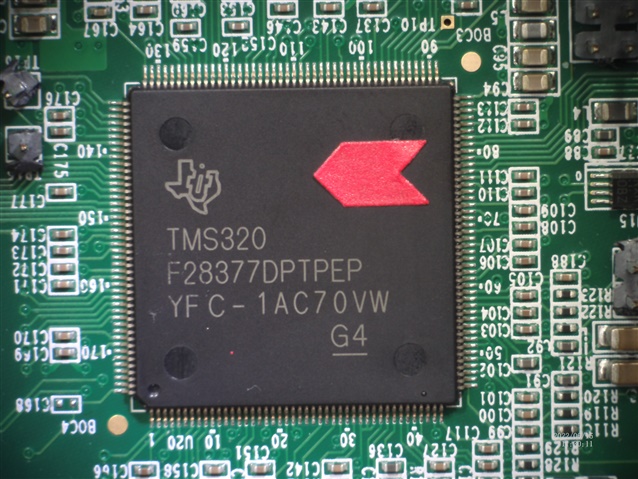
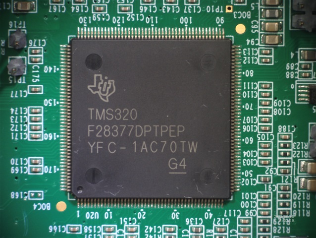
Due to the shortages of the 'TMS320F28377D' processor for our production runs we recently changed to using the TMS320F28377D-EP variant which was available despite its price difference. We made this decision based on this forum post: https://e2e.ti.com/support/microcontrollers/c2000-microcontrollers-group/c2000/f/c2000-microcontrollers-forum/1053170/tms320f28377d-ep-commercial-and-ep-difference

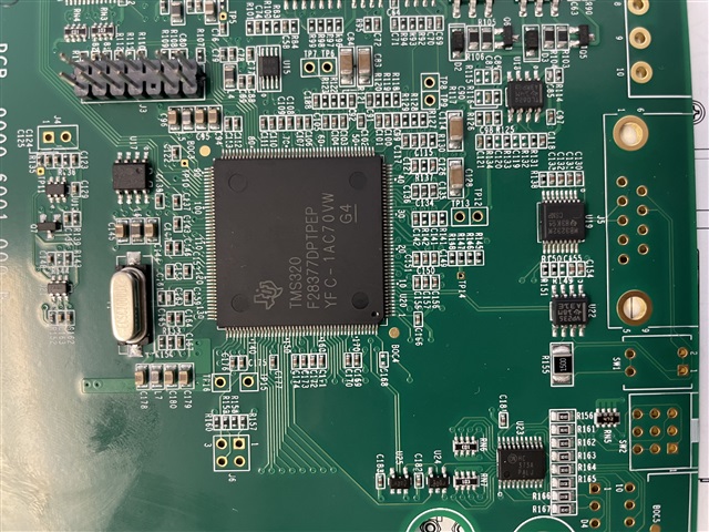
In our first production batch we have had 10 of our 200 board batch fail quality control during flash programming issues. We have produced over 700 of the same production boards previously using the TMS320F28377D processor without a single instance of flash programming difficulties. We have attempted to program these 10 failing boards using the following methods: Serial Flash, Uniflash, and CCS. We have tried both serial and the XDS2XX USB Debug Probe.

We've run out of ideas to for potential causes for these failures. We have checked the first couple returns from QC for bad traces, and any other physical level problems and found none. 

I have trace logs from both Serial Flash programming and Uniflash if those will help. However the serial ones are quite large so if those are wanted I will send separately. 


Here is the log from UniFlash:

volume_upVerboseClearClose
[6/3/2022, 10:52:01 AM] [INFO] C28xx_CPU1: GEL Output: Memory Map Initialization Complete
[6/3/2022, 10:52:01 AM] [INFO] C28xx_CPU2: GEL Output: Memory Map Initialization Complete
[6/3/2022, 10:52:02 AM] [INFO] C28xx_CPU1: Performing Security Operation...
[6/3/2022, 10:52:02 AM] [INFO] C28xx_CPU1: Calculated Link Pointer Offset: 0x20
[6/3/2022, 10:52:02 AM] [INFO] C28xx_CPU1: Unlocking device...
[6/3/2022, 10:52:02 AM] [INFO] C28xx_CPU1: Lock status: 0
[6/3/2022, 10:52:02 AM] [SUCCESS] C28xx_CPU1: Operation completed successfully.
[6/3/2022, 10:52:07 AM] [INFO] C28xx_CPU1: GEL Output: Memory Map Initialization Complete
[6/3/2022, 10:52:07 AM] [INFO] C28xx_CPU2: GEL Output: Memory Map Initialization Complete
[6/3/2022, 10:52:08 AM] [INFO] C28xx_CPU1: Writing Flash @ Address 0x00080000 of Length 0x00000002 (page 0)
[6/3/2022, 10:52:09 AM] [ERROR] C28xx_CPU1: Error: (Error -1044 @ 0x0) The debug probe reported an error. Confirm debug probe configuration and connections, reset the debug probe, and retry the operation. (Emulation package 9.6.0.00172)
[6/3/2022, 10:52:09 AM] [ERROR] C28xx_CPU1: Trouble Halting Target CPU: (Error -1135 @ 0xC095) The debug probe reported an error. Confirm debug probe configuration and connections, reset the debug probe, and retry the operation. (Emulation package 9.6.0.00172)
[6/3/2022, 10:52:09 AM] [ERROR] C28xx_CPU1: Unable to determine target status after 20 attempts
[6/3/2022, 10:52:09 AM] [ERROR] C28xx_CPU1: Failed to remove the debug state from the target before disconnecting. There may still be breakpoint op-codes embedded in program memory. It is recommended that you reset the emulator before you connect and reload your program before you continue debugging
[6/3/2022, 10:52:09 AM] [ERROR] C28xx_CPU1: Error occurred during flash operation: Could not read 0x0007026D@Data: target is not connected
[6/3/2022, 10:52:09 AM] [ERROR] C28xx_CPU1: Error occurred during flash operation: Could not write 0x0005F444@Data: target is not connected
[6/3/2022, 10:52:09 AM] [ERROR] C28xx_CPU1: Error occurred during flash operation: Could not read 0x0005F444@Data: target is not connected
[6/3/2022, 10:52:09 AM] [ERROR] C28xx_CPU1: Error occurred during flash operation: Could not read 0x000130@Program: target is not connected
[6/3/2022, 10:52:09 AM] [INFO] C28xx_CPU1: PLL configuration status = 0.
[6/3/2022, 10:52:09 AM] [ERROR] C28xx_CPU1: Error executing PLL configuration algorithm. Operation cancelled. (0x0)
[6/3/2022, 10:52:09 AM] [ERROR] C28xx_CPU1: Error occurred during flash operation: Could not write 0x0005D200@Data: target is not connected
[6/3/2022, 10:52:09 AM] [ERROR] C28xx_CPU1: File Loader: Memory write failed: Unknown error
[6/3/2022, 10:52:09 AM] [ERROR] C28xx_CPU1: Error occurred during flash operation: Could not read register PC: target is not connected
[6/3/2022, 10:52:09 AM] [ERROR] C28xx_CPU1: Error occurred during flash operation: Could not write 0x0005F800@Data: target is not connected
[6/3/2022, 10:52:09 AM] [ERROR] C28xx_CPU1: Error occurred during flash operation: Could not write 0x000000@Program: target is not connected
[6/3/2022, 10:52:09 AM] [ERROR] C28xx_CPU1: Error occurred during flash operation: Cannot enable while the target is disconnected
[6/3/2022, 10:52:09 AM] [ERROR] C28xx_CPU1: Error occurred during flash operation: Could not read 0x0005F444@Data: target is not connected
[6/3/2022, 10:52:09 AM] [ERROR] C28xx_CPU1: Error occurred during flash operation: Could not read 0x0007026D@Data: target is not connected
[6/3/2022, 10:52:09 AM] [ERROR] C28xx_CPU1: Error occurred during flash operation: Could not write 0x0005F444@Data: target is not connected
[6/3/2022, 10:52:09 AM] [ERROR] C28xx_CPU1: Error occurred during flash operation: Could not read 0x0005F444@Data: target is not connected
[6/3/2022, 10:52:09 AM] [ERROR] C28xx_CPU1: Error occurred during flash operation: Failed to run target while trying to execute pwrite_en.alg
[6/3/2022, 10:52:09 AM] [ERROR] C28xx_CPU1: Flash operation timed out waiting for the algorithm to complete. Operation cancelled.
[6/3/2022, 10:52:09 AM] [ERROR] C28xx_CPU1: Perform a debugger reset and execute the Boot-ROM code (click on the RESUME button in CCS debug window) before erasing/loading the Flash. If that does not help to perform a successful Flash erase/load, check the Reset cause (RESC) register, NMI shadow flag (NMISHDFLG) register and the Boot-ROM status register for further debug.
[6/3/2022, 10:52:09 AM] [ERROR] C28xx_CPU1: Error occurred during flash operation: Could not read 0x0007026D@Data: target is not connected
[6/3/2022, 10:52:09 AM] [ERROR] C28xx_CPU1: Error occurred during flash operation: Could not write 0x0005F444@Data: target is not connected
[6/3/2022, 10:52:09 AM] [ERROR] C28xx_CPU1: Error occurred during flash operation: Could not read 0x0005F444@Data: target is not connected
[6/3/2022, 10:52:09 AM] [ERROR] C28xx_CPU1: Error occurred during flash operation: Could not read 0x0007026D@Data: target is not connected
[6/3/2022, 10:52:09 AM] [ERROR] C28xx_CPU1: Error occurred during flash operation: Could not write 0x0005D200@Data: target is not connected
[6/3/2022, 10:52:09 AM] [ERROR] C28xx_CPU1: Error occurred during flash operation: Could not read 0x05D200@Program: target is not connected
[6/3/2022, 10:52:09 AM] [ERROR] C28xx_CPU1: Error occurred during flash operation: Could not read 0x0007026D@Data: target is not connected
[6/3/2022, 10:52:09 AM] [ERROR] C28xx_CPU1: Error occurred during flash operation: Could not read 0x0005D20E@Data: target is not connected
[6/3/2022, 10:52:09 AM] [ERROR] C28xx_CPU1: Error occurred during flash operation: Could not write 0x0005D20E@Data: target is not connected
[6/3/2022, 10:52:09 AM] [ERROR] C28xx_CPU1: Error occurred during flash operation: Could not read 0x0005D20E@Data: target is not connected
[6/3/2022, 10:52:09 AM] [ERROR] C28xx_CPU1: Error occurred during flash operation: Could not write 0x0005D20E@Data: target is not connected
[6/3/2022, 10:52:09 AM] [ERROR] C28xx_CPU1: Error occurred during flash operation: Could not read 0x0005D22E@Data: target is not connected
[6/3/2022, 10:52:09 AM] [ERROR] C28xx_CPU1: Error occurred during flash operation: Could not read 0x0005D208@Data: target is not connected
[6/3/2022, 10:52:09 AM] [ERROR] C28xx_CPU1: Error occurred during flash operation: Could not write 0x0005D208@Data: target is not connected
[6/3/2022, 10:52:09 AM] [ERROR] C28xx_CPU1: Error occurred during flash operation: Could not read 0x0005D208@Data: target is not connected
[6/3/2022, 10:52:09 AM] [ERROR] C28xx_CPU1: Error occurred during flash operation: Could not write 0x0005D208@Data: target is not connected
[6/3/2022, 10:52:09 AM] [ERROR] C28xx_CPU1: Error occurred during flash operation: Could not read 0x0005D222@Data: target is not connected
[6/3/2022, 10:52:09 AM] [ERROR] C28xx_CPU1: Error occurred during flash operation: Could not write 0x0005D222@Data: target is not connected
[6/3/2022, 10:52:09 AM] [ERROR] C28xx_CPU1: Error occurred during flash operation: Could not write 0x0005D214@Data: target is not connected
[6/3/2022, 10:52:09 AM] [ERROR] C28xx_CPU1: Error occurred during flash operation: Could not read 0x0005D20E@Data: target is not connected
[6/3/2022, 10:52:09 AM] [ERROR] C28xx_CPU1: Error occurred during flash operation: Could not write 0x0005D20E@Data: target is not connected
[6/3/2022, 10:52:09 AM] [ERROR] C28xx_CPU1: Error occurred during flash operation: Could not write 0x0005D20E@Data: target is not connected
[6/3/2022, 10:52:09 AM] [ERROR] C28xx_CPU1: Error occurred during flash operation: Could not write 0x0005D222@Data: target is not connected
[6/3/2022, 10:52:09 AM] [ERROR] C28xx_CPU1: Error occurred during flash operation: Could not write 0x0005D200@Data: target is not connected
[6/3/2022, 10:52:09 AM] [ERROR] C28xx_CPU1: Error occurred during flash operation: Could not write 0x000000@Program: target is not connected
[6/3/2022, 10:52:09 AM] [ERROR] C28xx_CPU1: Error occurred during flash operation: Cannot enable while the target is disconnected
[6/3/2022, 10:52:09 AM] [ERROR] C28xx_CPU1: Error occurred during flash operation: Could not read 0x0005F444@Data: target is not connected
[6/3/2022, 10:52:09 AM] [ERROR] C28xx_CPU1: Error occurred during flash operation: Could not read 0x0007026D@Data: target is not connected
[6/3/2022, 10:52:09 AM] [ERROR] C28xx_CPU1: Error occurred during flash operation: Could not write 0x0005F444@Data: target is not connected
[6/3/2022, 10:52:09 AM] [ERROR] C28xx_CPU1: Error occurred during flash operation: Could not read 0x0005F444@Data: target is not connected
[6/3/2022, 10:52:09 AM] [ERROR] C28xx_CPU1: Error occurred during flash operation: Failed to run target while trying to execute pwrite_dis.alg
[6/3/2022, 10:52:09 AM] [ERROR] C28xx_CPU1: Flash operation timed out waiting for the algorithm to complete. Operation cancelled.
[6/3/2022, 10:52:09 AM] [ERROR] C28xx_CPU1: Perform a debugger reset and execute the Boot-ROM code (click on the RESUME button in CCS debug window) before erasing/loading the Flash. If that does not help to perform a successful Flash erase/load, check the Reset cause (RESC) register, NMI shadow flag (NMISHDFLG) register and the Boot-ROM status register for further debug.
[6/3/2022, 10:52:09 AM] [ERROR] C28xx_CPU1: Error occurred during flash operation: Could not read 0x0007026D@Data: target is not connected
[6/3/2022, 10:52:09 AM] [ERROR] C28xx_CPU1: Error occurred during flash operation: Could not write 0x0005F444@Data: target is not connected
[6/3/2022, 10:52:09 AM] [ERROR] C28xx_CPU1: Error occurred during flash operation: Could not read 0x0005F444@Data: target is not connected
[6/3/2022, 10:52:09 AM] [ERROR] C28xx_CPU1: Error occurred during flash operation: Could not write register PC: target is not connected

-Ben


  • Hi Ben,

    Thank you for the information.

    How are the boot mode pins configured when programming these fresh parts?  Hope they are configured for wait boot.

    Thanks and regards,

    Vamsi

  • Yes, the boot pins are configured using a jumper which is removed after programming. All of the drives appear to be in wait boot mode and we can load the Serial Flash Kernel into RAM and execute it. However, when we send commands to the serial flash kernel, it responds with an error.

    Ben

  • Ben,

    For Serial flash kernel, did not you use the SCI boot?

    Thanks and regards,

    Vamsi

  • Yes, We jumper the SCI boot pins together for the 20 or so different production variants we produce.

  • Ben,

    I hope you meant to say you configured the boot mode pins to SCI boot mode.

    Ok, I will assign this to our SCI kernel expert.  Please send the kernel failure logs to her.

    Thanks and regards,

    Vamsi 

  • Yes, that was what I meant.

    Thanks,

    Ben

  • Ok Ben, thank you for the clarification.  I assigned to our SCI kernel expert.

    Thanks and regards,
    Vamsi

  • Ben, 

    Can you post the serial flash programmer output here?

    Anu

  • I don't have a drive available to me till Monday. Is it possible to use the Uniflash output I included in the original post. Uniflash is also failing.

    Ben

  • Ben, 

    For Uniflash, Vamsi may be able to help better. Let me know once you have the kernel log outputs. 

    Anu

  • Here is the output from the serial Flash Programmer.  The Kernel loads, I get the menu, I select 1-DFU CPU 1 and get a NACK reply.../

    Bit rate /s of transfer was: 499.738434
    Kernel loaded! Booting kernel...
    Done waiting for kernel boot...
    Attempting autobaud to send function message...
    What operation do you want to perform?
             1-DFU CPU1
             2-DFU CPU2
             3-Erase CPU1
             4-Erase CPU2
             5-Verify CPU1
             6-Verify CPU2
             7-Unlock CPU1 Zone 1
             8-Unlock CPU1 Zone 2
             9-Unlock CPU2 Zone 1
            10-Unlock CPU2 Zone 2
            11-Run CPU1
            12-Reset CPU1
            13-Run CPU1 and Boot CPU2
            14-Reset CPU1 and Boot CPU2
            15-Run CPU2
            16-Reset CPU2
             0-DONE
    1
    
    calling f021_SendPacket
    
    NACK Error with sending the Function Packet... Please press Ctrl-C to abort.Downloading .\9000_6010_000_CPU1.hex to device...

  • It would be nice if we could at least resolve the Uniflash issue. We sincerely hope this isn't an internal processor issue causing us to scrap these boards. It's hard enough getting any processors from TI right now.

    Ben

  • Were any modifications made to the flash kernel or host progammer? If so, what are they? 

  • No, there are no modifications between the circuit boards with processors that do program and the circuit boards with processors which receive the above messages.  The Serial Firmware Update kernels we are using are the ones exactly provided by TI with no modifications. Please also note that Uniflash is also not working to program these processors (as reported in the original post). We have 90% of our production circuit boards with these processors flashing correctly and working, it is only 10% of our boards which are not working.

    Ben

  • Ben, 

    Thanks for the info. Given that the majority of the boards with the EP variant work and that the kernels have not been changed, I will ask the apps expert to help you on finding out what is happening with the remaining boards. 

    Anu

  • I have been told that production is currently on hold for the remainder of the 700 batch until we can determine a solution for this issue. We are to ship 100 per month to our customer...

    Ben

  • Ben,

    The -EP material should be form/fit/function equivalent to the non -EP so I've got no reason to suspect that as the root cause, but agree that something is behaving differently here whatever the reason.

    1)Device Information

    Would it be possible to take a picture of the top side of the C2000 device and attach it here?  If you prefer you can just reply back with the characters you see.  This will let me get some basic information on when this material was manufactured, etc.

    I'm assuming that most/all of the 700pcs are from the same range, but if you could note a few that are failing and some that are not failing that will help as well.

    If you have an equivalent from the catalogue device you were previously using that will also be helpful.

    At this point trying to track down any commonality good vs bad that we can use to investigate internally here.

    2)Debug Information

    -If you connect through JTAG with CCS and don't program the flash, do you note any stability issues with that connection?  If you could load a C2000Ware example that is RAM based only.  Or perform a simple erase operation with CCS and note on the bad devices if that is OK or not.

    -Is the programming process on your end more automated or manual, here I'm looking to see how long the device is powered before you attempt to connect/program if this very automated, I would want to see if we give the device longer to stabilize before programming does that help things, etc. 

    -If possible can we scope the VDDIO (3.3V) rail good/bad when programming to see if there are any obvious stability issues where the supply droops more than the other?

    From the previous posts it sounds like the act of programming the flash, no matter the interface, causes an error on these devices but will be good to make sure that is 100% the case.

    Best,

    Matthew

  • Here are the pictures of two of the boards, labeled good and bad. The batch appears to be different, I will have production do a second check of the other chips. Purchasing did a check on the batch purchase and told me they all appear to be the same batch and were ordered/delivered at the same time. 

    Bad BoardGood Board

    The programming process is 100% manual. We need to test a number of things and make adjustments to pots prior to firmware programming. Normally the power board has warmed up at this point so we don't believe it is a power stabilization issue.

    The bad boards are not running any RAM programming through CCS, it immediately disconnects. Erasing is also not working.

    I will work on getting the oscilloscope test done next.  I am using the same power board for both.

  • Here are a couple more pictures from Production. Any chips with a red marker are considered bad and marked for potential rework. These are from the same batch.

    Bad BoardGood Board

  • Ben,

    Thanks for the additional info, as you mention these are all from the same batch and date code(last row) indicates these are recent material:  "1A" indicates that these were manufactured in Nov 2021.

    The fact that you can't connect at all with CCS, much less load to RAM or Flash, is helpful debug wise.

    Please comment on the following:

    1)Value of the pulldown resistor on the TRSTn pin on your PCB

    2)Can you comment on how you have configured the boot mode pins, GPIO72 and GPIO84

    If configured for a peripheral boot, if possible on a bad board change this to Wait Boot Mode(see below image) and see if this changes anything in terms of the CCS connection ability? 

    If you are able to connect, are you able to load a program, either to RAM(like a C2000Ware example) or your flash image?

    Best,
    Matthew

  • Hi Matthew,

    This is Lily, Ben's senior Engineer.

    I have some addition information regarding test CCS when loading program to RAM on a 'BAD board'.

    I was able to connect and load to RAM without any issue, but during the execution, the debugger sometimes was disconnected and sometimes not. It depends on the system clock setup. 

    Here are some examples:

    Working:

    1. With Internal clock, IMULT= 1 and 2 with OSCCLKSRCSEL= 0 (INTOSC2),

    InitSysPll(INT_OSC2,IMULT_2,FMULT_1,PLLCLK_BY_1);working

    2.   With External clock, IMULT= 1, OSCCLKSRCSEL = 1 (External Oscillator, XTAL). External clock is 20MHz

     InitSysPll(XTAL_OSC,IMULT_1,FMULT_1,PLLCLK_BY_1); working

    Not working:

    1. With Internal Clock

    InitSysPll(INT_OSC2,IMULT_3,FMULT_1,PLLCLK_BY_1); Not working

    2. With External Clock

     InitSysPll(XTAL_OSC,IMULT_2,FMULT_1,PLLCLK_BY_1);  Not working

     Or InitSysPll(XTAL_OSC,IMULT_2,FMULT_1,PLLCLK_BY_2); Not working

    Here is the error message when debugger was disconnected during the running

    C28xx_CPU1: Error: (Error -1044 @ 0x0) The debug probe reported an error. Confirm debug probe configuration and connections, reset the debug probe, and retry the operation. (Emulation package 9.3.0.00042)

    I have replaced the external clock as well. The board behaved the same.

    Best Regards,

    Lily

  • Lily,

    Can you try and use one of the examples in C2000Ware on the "bad" board, for instance the path:

    C:\ti\c2000\C2000Ware_4_01_00_00\driverlib\f2837xd\examples\cpu1\dma\ has a simple DMA example, but the key here is that the PLL is setup for 200MHz based on 20MHz external clock.  (I think all the driverlib examples do this)

    I want to see if this also fails, or runs OK.  There are some particular steps we are following in the SysCtl_setClock() function to set the PLL I would like to if they matter here, not knowing if your code is using this or not.

    Is the final target system clock for your application 200MHz, or is the not working examples you gave the final clock rate?

    If above fails as well, I'd like to monitor the VDDIO/VDD supplies as we increase the chip frequency to see if we notice any droop as the device demand more current.

    Best,

    Matthew

  • Hi Matthew,

    Thanks for your support!

    Here are the answers to your suggestions and questions:

    1. Ran the C2000 DMA example project on the 'bad' board, it failed as well;

    2. Our application system clock is 200MHz. We have been shipping F28377D products since early-2017 with this system clock frequency;

    3. Monitored VDDIO and VDD on the 'bad' board from system clock 5MHz to 20MHz, did not notice any differences.

    Best Regards,

    Lily

  • Lily,

        Matt is out-of-the-office for a week. In the interim, I will help you. Please give me a day to analyze this.

  • Thank you for helping!

    Lily

  • Ben,

              Going through the history, this doesn’t appear to be a problem with the flash per se. Your statement “The bad boards are not running any RAM programming through CCS, it immediately disconnects” is key. If this doesn’t work, nothing else is going to work. For flash programming to succeed, the programming algorithms need to execute fine from RAM. Since you are able to connect to the device via CCS, at least the scan chain is working correctly. 

    Lily,

              In all the “Not working” cases, the operating frequency (SYSCLKOUT) of the device is still well below the rated frequency of 200 MHz, so it is intriguing why you are seeing a failure. Am I correct that you are unable to run any C2000ware example “as is”? Can you share your schematics with me privately? You can do this by initiating a “friendship” request.

  • Hi Hareesh,

    You are correct, I was not able to run C2000ware as is.

    Thank you!

    Lily

  • Lily,

                  I looked at the schematics and couldn’t find an issue in the circuitry connected to some of the critical MCU pins (Reset, JTAG etc). In any case, you have programmed 700 of these boards with the non-EP part without any issues. Even with the EP part, you only have an issue with 10 out of 200 devices. If this is correct, I am only inclined to suspect something with these 10 devices.

  • Hi Hareesh, 

    Thank you for taking your time checking!

    Yes, you are correct. We have shipped 200pcs products with -EP, 10pcs -EP boards have issues. There are 190 more -EP in process (built, not tested), and over 300 pcs MCU IC in stock, not built (waiting for engineering decisions).  

    Best Regards,

    Lily

  • Lily,

              I am confused.

    We have shipped 200pcs products with -EP,

    So, you have successfully programmed and shipped 200 of your products with the -EP parts?

    And you now have 10 EP boards where you have already seen the failure? And 190 boards built but not tested?

    If the above is true, is the LOT trace code the same for all the 10 failing parts?

  • Hareesh,

    1. Yes, we have successfully programmed and shipped 200 products with the -EP parts;

    2. Yes, we have 10 EP boards where you have already seen the failure, these are the boards failed during testing the first shipped 210pcs products;

    3. Yes, 190 boards built but not tested.

    4. I am sure there are some Good and BAD ones that have the same LOT code.

    Best Regards,

    Lily

  • Lily,

          Is the table below correct?

    Clock source

    PLLMULT

    PLL-DIV

    Status

    INTOSC2

    x1, x2

    /1

    OK

    20 MHz XTAL

    x1

    /1

    OK

    INTOSC2

    x3

    /1

    Not OK

    20 MHz XTAL

    x2

    /1

    Not OK

    20 MHz XTAL

    x2

    /2

    Not OK

    Specifically, I want to confirm the highlighted row. i.e. the device worked fine for some combination of the PLL multiplier and divider with an external crystal.

    I also wanted to bring to your attention the following item in page 21 of the errata (www.ti.com/lit/SPRZ412) PLL: May Not Lock on the First Lock Attempt. Can you evaluate if this could be at play?

  • Hi Hareesh,

    Sorry, the test results are not consistent. I don't know why.

    Ran the test again, here is the result:

    Clock source

    PLLMULT

    PLL-DIV

    Status

    INTOSC2

    x1, x2

    /1

    OK

    20 MHz XTAL

    x1

    /1

    OK

    INTOSC2

    x3

    /1

    Not OK

    20 MHz XTAL

    x2

    /1

    Not consistent, sometimes OK

    Most of the time not OK 

    20 MHz XTAL

    x2

    /2

    OK, (But remembered 'was not OK' when tested last week)

    Regarding 'page 21 of the errata (www.ti.com/lit/SPRZ412)'. Here is the PLL code:

    EALLOW;
    //modfiy dividers to maximum to reduce the inrush current
    ClkCfgRegs.SYSPLLMULT.bit.IMULT = imult; //Setting integer multiplier
    ClkCfgRegs.SYSPLLMULT.bit.FMULT = fmult; //Setting fractional multiplier
    ClkCfgRegs.SYSPLLCTL1.bit.PLLEN = 1; //Enable SYSPLL
    EDIS;

    //Wait for the SYSPLL lock
    while(ClkCfgRegs.SYSPLLSTS.bit.LOCKS != 1)
    {
    // Uncomment to service the watchdog
    // ServiceDog();
    }

    EALLOW;
    ClkCfgRegs.SYSPLLCTL1.bit.PLLCLKEN = 1;
    EDIS;

    When the PLL did not work, code was lost as soon as the highlighted line was executed.

    Best Regards,

    Lily

  • Lily,

        Did you implement the workaround? (which suggests five lock sequences)

  • Hi Hareesh,

    Would you mind sending me the workaround example code?

    Thanks,

    Lily

  • Please refer to SysCtl_setClock() in sysctl.c file in C2000ware. This is also mentioned in the Errata workaround.

  • Hareesh,

    I had run C2000ware example code last week as Matthew suggested. It failed.

    MatthewPate's suggestion:

    'C:\ti\c2000\C2000Ware_4_01_00_00\driverlib\f2837xd\examples\cpu1\dma\ has a simple DMA example, but the key here is that the PLL is setup for 200MHz based on 20MHz external clock.  (I think all the driverlib examples do this)'

    I retested again today. It failed as well.

    Best Regards,

    Lily

  • Lily,

       Will discuss with Matt the next course of action. Will let you know by EOB Monday. Thank you for your patience.

  • Lily,

    1)Based on the info we have thus far, we'd like to get a few of the failing devices back to TI for re-test/evaluation to see if we can reproduce the issue.  This will require the devices to be removed from your PCB and shipped back to TI, please see this page on how to start this procedure(there are different scenarios depending on if the purchase was direct from TI or through a distributor).

    Let me know if you have any issues/questions on this process.  We can use this E2E thread as evidence that TI is approving shipping 2-3 failing devices back to us for evaluation.

    2)Thinking more about the issue in your system, would it be possible to single step through the code(you can use the DMA example that fails) to pin point the C instruction that causes things to go bad?  I'm assuming its when we change the PLL multipliers, but it would be good to confirm.

    Best,

    Matthew

  • Hi Matthew,

    1. We will send a few BAD MCUs back to TI.

    2. The code was failed after the following step

    // Enable PLLSYSCLK is fed from system PLL clock
    //
    HWREGH(CLKCFG_BASE +
    SYSCTL_O_SYSPLLCTL1) |= SYSCTL_SYSPLLCTL1_PLLCLKEN;

    Best Regards,

    Lily

  • Thanks Lily, we will be on the look out for these.  If you get any confirmation emails from TI on the returns if you could let me know as well, like case #, etc that will help.

    This appears to be PLL related as we thought previously, will see if we can reproduce once we get the devices in house.

    Best,

    Matthew