Because of the holidays, TI E2E™ design support forum responses will be delayed from Dec. 25 through Jan. 2. Thank you for your patience.

This thread has been locked.

If you have a related question, please click the "Ask a related question" button in the top right corner. The newly created question will be automatically linked to this question.

TMS320F28377D: TMS320F28377D implementation (beginner)

Part Number: TMS320F28377D
Other Parts Discussed in Thread: C2000WARE, UNIFLASH

This is my first time implementing any kind of microcontroller into a design. I'm using the TMS320F28377DZWTT. I have several of the launch pad dev boards but I would like to move towards more of a production design with minimal components. I have not included U6 (FT2232HQ-REEL) in my design.

Instead, I have connected C19 and B19 directly to USB DP/DM.

If I apply 1.2V between VDD and VSS, 3.3 between VDDIO and VSS, should I be able to expect to communicate with the chip via USB through the CCS terminal?

Are there other steps that need to be completed before?

  • Eric,

    Thanks for reaching out. 

    The above will not work for interfacing the device with CCS.  The FT2232 has been programmed to act as the emulator(in this case an XDS100v2) to connect the C2000 to CCS.  This is taking the USB signals and creating the JTAG signals, TDO/TDI/TMS/TCK/TRSTn that the F2837xD device uses to access the test port.  You should see these coming out of the isolators U5 and U7 on the schematic.

    While the above would allow you to interact with the on-chip USB module, we do not support a debug connection through this interface.

    For a more production purpose PCB I agree with eliminating the FT2232, but for debug you will need to bring the JTAG signals from the C2000 MCU to a standard header(either TI 14-pin or TI 20pin) and buy an XDS110 or XDS200 external emulator pod to connect with CCS.

    Let me know if I can provide more resources to get you started.  You can check out the F2837xD experimenter kit, base board to see the 14-pin connection PN.

    Best,

    Matthew

  • Matt,

    Thank you so much for responding.

    I have connected the JTAG signals to a 10-pin connector. I'll probably need to create a custom cable to re-arrange the signals.

    I have a XDS110 on order.

    Assuming I match the correct signals; TDO/TDI/TMS/TCK/TRSTn, with the debug probe, I should be able to communicate with the chip?

    How will I communicate with the chip with out the probe through USB?

  • Eric,

    This is correct, with the signals connected properly you should be good to go connecting to CCS.

    If you want to use just the USB only, then you would need to create some functions/drivers in C to handle whatever data you want to share back and forth over the USB.  If it is simply memory copying, I believe we have some bulk data examples for the USB in C2000Ware.

    Best,

    Matthew

  • Thank you Matthew

  • Hello Mathew,

    I checked all of the connection as stated above but I'm still getting the following error:

    Error connecting to the target: (Error -267 @ 0x0) The controller could not detect valid target supply. Check target JTAG connection and/or connection setting specifying voltage level. (Emulation package 9.6.0.00172)

    I'm using the XDS110 debugger and TI's Uniflash to program the microcontroller. I'm using the same code as before on the Launch-F28379D 

    Is there something I'm missing?

    Is there some demo or test code that can be flashed onto the microcontroller to verify it's operation?

    -Eric

  • Eric,

    Apologies on omitting the JTAG PD signal.  This is just a check the emulator uses to see if there is power applied to the device/PCB.  You can short this to your VDDIO(3.3V) on the PCB.  PD should be defined on the pin header, you may have just floated this on the connector on your PCB.

    There is no formal PD signal/pin from the C2000 device, its just assumed to connect to the VDDIO supply of the device.

    Best,

    Matthew

  • Matthew,

    I wasn't able to find the signal PD anywhere on the XDS110 probe guide. Is it called something else? Maybe VTref?

    If I need a VDDIO reference voltage, I would think that I need a ground too.

    -Eric

  • Eric,

    Yes, it is VTREF, and you are correct on the ground.

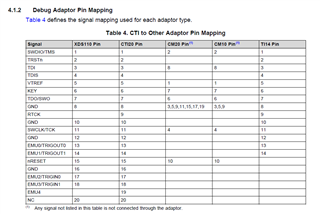
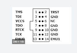
    We typically use the TI 14-pin header with our C2000 devices, although the same signals exist (and more) on the TI 20pin. 

    This is in the XDS110 guide, but copying it here for reference

    and the 14pin map

  • Here is BOM info on the header as well, do a ctrl-f on the page for 14-pin

    https://software-dl.ti.com/ccs/esd/documents/xdsdebugprobes/emu_jtag_connectors.html

    Best,

    Matthew

  • I connected everything up.

    But now I'm getting a new error:

    Error connecting to the target: (Error -2131 @ 0x0) Unable to access device register. Reset the device, and retry the operation. If error persists, confirm configuration, power-cycle the board, and/or try more reliable JTAG settings (e.g. lower TCLK). (Emulation package 9.6.0.00172)

    I tried power cycling the device (turning off/on 1.2V also tried turning off/on 1.2V then 3.3V) then loading the image again and it gets stuck at:

    GEL Expression: OnPreTargetConnect()

    Any suggestions?

    Do you think the chip is damaged? Is there anyway to tell?

  • Eric,

    Can you try and put the device in Wait Boot mode and see if this helps after power cycling:

    Also, if you double click your ccxml file and "Test Connection" can you report back what that returns in the dialogue box?

    Best,

    Matthew

  • Sorry Matthew could you clarify your instructions?

    How do I go about putting the device in Wait Boot mode? I don't I have access to either GPIO72 or GPIO84.

    Loaded the ccxml file into CCS, "Test Connection"

    [Start: Texas Instruments XDS110 USB Debug Probe]

    Execute the command:

    %ccs_base%/common/uscif/dbgjtag -f %boarddatafile% -rv -o -S integrity

    [Result]


    -----[Print the board config pathname(s)]------------------------------------

    C:\Users\egk\AppData\Local\Texas Instruments\
    CCS\ccs1040\0\0\BrdDat\testBoard.dat

    -----[Print the reset-command software log-file]-----------------------------

    This utility has selected a 100- or 510-class product.
    This utility will load the adapter 'jioxds110.dll'.
    The library build date was 'Jun 25 2021'.
    The library build time was '11:45:30'.
    The library package version is '9.4.0.00129'.
    The library component version is '35.35.0.0'.
    The controller does not use a programmable FPGA.
    The controller has a version number of '5' (0x00000005).
    The controller has an insertion length of '0' (0x00000000).
    This utility will attempt to reset the controller.
    This utility has successfully reset the controller.

    -----[Print the reset-command hardware log-file]-----------------------------

    The scan-path will be reset by toggling the JTAG TRST signal.
    The controller is the XDS110 with USB interface.
    The link from controller to target is direct (without cable).
    The software is configured for XDS110 features.
    The controller cannot monitor the value on the EMU[0] pin.
    The controller cannot monitor the value on the EMU[1] pin.
    The controller cannot control the timing on output pins.
    The controller cannot control the timing on input pins.
    The scan-path link-delay has been set to exactly '0' (0x0000).

    -----[An error has occurred and this utility has aborted]--------------------

    This error is generated by TI's USCIF driver or utilities.

    The value is '-233' (0xffffff17).
    The title is 'SC_ERR_PATH_BROKEN'.

    The explanation is:
    The JTAG IR and DR scan-paths cannot circulate bits, they may be broken.
    An attempt to scan the JTAG scan-path has failed.
    The target's JTAG scan-path appears to be broken
    with a stuck-at-ones or stuck-at-zero fault.

    [End: Texas Instruments XDS110 USB Debug Probe]

  • Eric,

              If this is a brand-new device (i.e. passwords have not been programmed and the device is unsecure), you should be able to connect without having to put the device in wait-boot mode. Wait boot mode is helpful when the device is secure which would prevent a successful JTAG connection. 

    It is always a good idea to provide access to GPIO72 and GPIO84, especially during the prototype phase. 

    Please provide the schematics to me privately (at least the JTAG portion). I can take a look. 

    I urge you to go through www.ti.com/lit/SPRACF0. It provides all the information you need to debug JTAG connectivity issues.

  • Yes, this is a brand-new device

    No problem providing the JTAG portion of the schematic

  • Eric,

        The information you provided is not adequate and hence not useful. You can share the schematics with me privately, without posting it on the forum. You can do this by initiating a friendship request with me. In the interim, please do go through SPRACF0.

  • I was able to flash the memory. Here are all the corrections I had to make

    1. Connect 3.3V on pin 1 for VTref

    2. Connect Gnd on pin 3 for Gnd

    3. Connect a 4.7K resistor from TRST to Gnd

    4. One of the settings in UniFlash is JTAG/SWD/cJTAG Mode. It's default is JTAG (114.9.1, SWD and cJTAG are disabled. This needs to be changed to cJTAG (1149.7) 4-pin standard mode

    Haraeesh and Matthew, thank you so much for all the information you provided and time you spent helping me.