This thread has been locked.

If you have a related question, please click the "Ask a related question" button in the top right corner. The newly created question will be automatically linked to this question.

SPI shift register and RXbuffer problems

Other Parts Discussed in Thread: TMS320F28055, TMS320F28035
Hello folks,
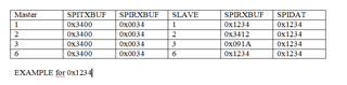
I have 2 controllers connected via spi, one is the master and the other is the slave. 
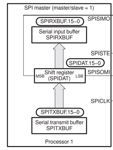
When I send data to the slave, the data arrives in the SPIDAT shift register.
The data should then be forwarded to the SPIRXBUF buffer.
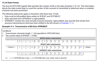
I also have to say that I send 2x 8 bits.
When I try to send data, it always arrives in the SPIDAT shift register, which can be seen in debug mode, but the data is not always in the SPIRXBUF, sometimes it pushes it in and sometimes not completely.
About 4 times it works and then 1 time it doesn't work again. Can someone tell me where the problem is.

thank you for your help.

Kind regards
Markus
  • Hello Markus, 

    Please provide more information.  What TI devices are used in this design? 

    A block diagram would be very helpful.

    Thank you,

    ~Leonard   


  • void spi_init(void)
    {

    //SpiaRegs.SPICCR.all = 0x0007; //Data is ready on rising edge), loopback is off, 8-bit data
    SpiaRegs.SPICTL.all = 0x000E; //Normal SPI clocking scheme(Data in latch on rising edge)master, 4-pin option, No interrupt
    SpiaRegs.SPICTL.bit.CLK_PHASE = 1; //1
    SpiaRegs.SPIBRR = 0x0077; //BateRate 0.5MHz

    SpiaRegs.SPICCR.all = 0x0087; //SPI is ready to transmit or receive the next character. TEST mit 16 bit 0x0087

    SpiaRegs.SPICCR.bit.CLKPOLARITY = 0; //0
    SpiaRegs.SPIPRI.bit.FREE = 1;
    }

    this is the code from my master i use the TMS320F28055

    void spi_init(void)
    {

    SpiaRegs.SPICCR.bit.SPISWRESET = 0;
    //SpiaRegs.SPICCR.all = 0x0007; //Data is ready on rising edge), loopback is off, 8-bit data

    //SpiaRegs.SPICTL.all = 0x000E; //Normal SPI clocking scheme(Data in latch on rising edge)master, 4-pin option, No interrupt
    SpiaRegs.SPICTL.all = 0x000A; //8 //Normal SPI clocking scheme(Data in latch on rising edge)slave, 4-pin option, No interrupt
    SpiaRegs.SPICTL.bit.CLK_PHASE = 1; //1
    SpiaRegs.SPIBRR = 0x0077; //BateRate 0.5MHz ist für den Slave nicht notwendig
    SpiaRegs.SPICCR.all = 0x0087; //SPI is ready to transmit or receive the next character.
    SpiaRegs.SPICCR.bit.CLKPOLARITY = 0; //0
    SpiaRegs.SPICTL.bit.SPIINTENA = 1 ;
    SpiaRegs.SPICTL.bit.OVERRUNINTENA = 1 ;
    SpiaRegs.SPIPRI.bit.FREE = 1;
    SpiaRegs.SPICCR.bit.SPISWRESET=1;
    }

    and this is the code from my slave  TMS320F28035

    I'm using an interrupt here, but I've also tried it without an interrupt

    uint16_t pdata = 0x1234;

    int dataH, dataL;
    dataH = 0;
    dataL = 0;

    dataH = (pdata >> 8);
    dataL = (pdata & 0x00FF);


    spi_xmit(dataH);
    spi_xmit(dataL);

    and with that I send example data in this case it would be the 0x1234 when I send it it arrives successfully in the shift register and buffer but if I want to send it more often the shift register does not completely shift the data into the buffer. to check I debug both microcontrollers at the same time. By the way, I send 8 bits twice in a row. the buffer has a size of 16 bits

  • the controllers are connected via the chipselect. then the clock is connected and then MISO-MISO and MOSI-MOSI as it should be with 2 controllers. the chipselect is permanently set to low so that data can be transmitted.

  • I made a table here. the example data i send was 0x1234
    the numbers under the slave and master are the number of times i sent the data. you can see that when the 6th sends, the data is correctly in the buffer again, but in between it doesn't send everything into the buffer.

  •   

    this diagram might be helpful. I got that from the technical reference manual from the f2803x. For me it's important that the data is completely in the buffer when I send it over from the controller because I want to process the data further. But if I can't ensure that the right data always arrives, it's difficult.

  • Markus,

    You didn't include your spi_xmit() function for the master, but you have to shift the 8-bit data to the MSB of the SPITXBUF register. This is because the SPITXBUF will get copied to the SPIDAT register, and the MSB will be shifted out first. In your spi_xmit() function, add data<<8, before writing to SPITXBUF.

  • hello gus this is my function for the master and slave

    Uint16 spi_xmit(int a)
    {
    Uint16 Ret_var = 0;

    SpiaRegs.SPITXBUF = (a << 8);
    while (SpiaRegs.SPISTS.bit.INT_FLAG == 0);

    Ret_var = SpiaRegs.SPIRXBUF << 8;
    return Ret_var;
    }

    i solved the problem when i send data from the master to the slave, the data is caught in the slave interrupt. after that i have to send spixmit(0x00) at the end of the interrupt. If I then send something from the master again, the data is correct in the RX buffer. but I still don't know why I always have to send 0x00 from the slave.

  • Markus,

    You don't have to shift the data when reading from SPIRXBUF. Please see diagram from the SPIDAT register below. Whenever SPICLK is active, the SPI will shift the SPIDAT MSB on the SIMO pin, and simultaneously shift in data from the SOMI pin on the LSB of SPIDAT. Therefore, for 8-bit character size, you have to shift data<<8 when writing to SPITXBUF, but you don't have to shift when reading from SPIRXBUF.

  • hello gus,
    maybe we misunderstood each other. I want to send several 16-bit data to the slave. When the data has arrived in the slave, 
    I want to save the data from the buffer in variables. I pushed the data as you said data <<8 from the master.
    The problem was if you send multiple 16-bit data, the slave cannot accept them all. I installed a delay after every 8 bits, which was necessary.
    With spi, the master transmits and the slave receives and transmits at the same time. So I had to send data from the master.
    Then catch the data in the slave interrupt, then store them in variables and send back 16 bits with 00.
    After that it worked when I send multiple data packets from the master. I think that's because of the shift register because the slave,
    otherwise always sends back the data that comes from the master automatically after every 16 bits and then at some point there is crap in the shift register and this hinders the master.
    if the slave sends back 16 bits 00 after each received, it works. Or do you think I did something wrong? I've tried many things but this is how it worked. or can you give me another advice.
    i connected 2 controllers via spi for the first time.
  • Markus,

    Apologies if I'm not fully comprehending your problem. Keep in mind that in slave configuration, you have to pre-load a value to the SPITXBUF register BEFORE the master starts generating clocks. Otherwise, the slave SPI will transmit whatever it has in the SPIDAT register at the time. However, you cannot write 2 8-bit characters back to back to SPITXBUF (unless you enable FIFO mode which I don't think you have enabled). You have to wait until the previous 8-bit character has been shifted out before writing the new character. You can use the BUFFULL_FLAG to determine when the SPI is ready for more data.

    This the sequence that should be followed for the slave, maybe it will help? I'm assuming no interrupts here.

    1. Wait for BUFFULL_FLAG == 0
    2. Write 0x12 to SPITXBUF ==> BUFFULL_FLAG should then be set to 1.
    3. Wait for BUFFULL_FLAG == 0 (master needs to send first 8-bit character here)
    4. Write 0x34 to SPITXBUF ==> BUFFULL_FLAG should then be set to 1.
    5. Repeat
  • hello gus,
    Thanks for your help. I didn't use FIFO mode. Do you know how to configure it correctly? I haven't used it before because the controllers I've used before didn't have it. I tried to configure it once but I didn't get the result I wanted. that's why I didn't activate it. I tried the example from TI. Does fifo mode have major benefits or are they only minimally noticeable?

  • hello gus,

    my current solution is that I send 16 bits from the SPITXBUF (master) and always wait for the FLAG bit BUFULL_FLAG == 0 as you said. I changed the 8 bit to 16 bit transmission. in the slave I intercept the value in the interrupt. and every time i intercepted it i send 00 from the slave back to the master also in 16 bit that's how it works till now. Do you maybe have a better solution with the FIFO mode, because I'm not so familiar with that. I would be grateful for an explanation.

  • Markus,

    I recently posted a brief explanation of the FIFO here:

    https://e2e.ti.com/support/microcontrollers/c2000-microcontrollers-group/c2000/f/c2000-microcontrollers-forum/1112888/explanation-of-fifo-mode-in-spi-tms320f28035/4124567?tisearch=e2e-sitesearch&keymatch=%25252520user%2525253A13605#4124567

    For more details you can refer to the technical reference manual. 

    I changed the 8 bit to 16 bit transmission. in the slave I intercept the value in the interrupt. and every time i intercepted it i send 00 from the slave back to the master also in 16 bit that's how it works till now.

    The only downside I see your approach is that by the time you get the interrupt, the SPI slave may already be shifting out a new value (depending on how fast the master starts the next character transaction). There is always that race condition, unless you can modify your master code to insert a delay between characters, assuming that is acceptable for your application. 

  • hello gus,
    thank you for your help. I have one more question, do you know if you have to synchronize the slave with the master? because the master doesn't know when the slave wants to send data. If I just keep clocking with the master, it's not synchronized. I notice that I always get different data from the slave, sometimes it works and sometimes it sends me strange data. is it because they need to be synchronized?

  • Markus,

    Once the master generates the first SPI CLK, the slave must start transmitting data. Whether that data is valid or not, depends on your application code. 

    You could implement "side band" signals similar to RTS/CTS in UART flow control. You could also assign and add START and END characters to your data and have the master discard any data outside that frame. You could have the master send X dummy characters, and expect valid data on the X+1 character. It really depends on your application.