This thread has been locked.

If you have a related question, please click the "Ask a related question" button in the top right corner. The newly created question will be automatically linked to this question.

TMS320F280049: ADC oversampling with hardware

Part Number: TMS320F280049
Other Parts Discussed in Thread: C2000WARE

Hi all,

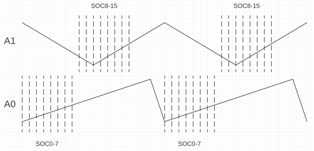
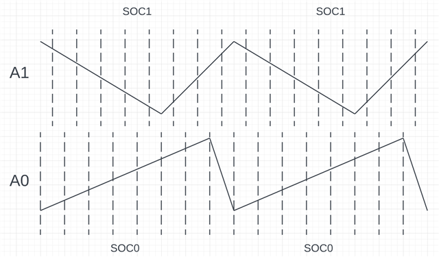
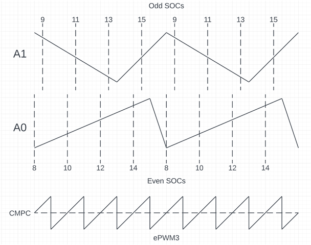
In my application, I have six analog signals, with each of the three ADCs sampling two of them, one on SOC0 and the other on SOC1. All SOCs are triggered via an ePWM (CMPC triggers EPWMxSOCA, which routes to SOC0 of each ADC, CMPD triggers EPWMxSOCB, which routes to SOC1 of each ADC). I also have my main real-time ISR which I execute every 10us. The ISR is triggered by one of the ADCINTs, and thus executes synchronously with all the ADC conversions.

Currently this means each signal is sampled once per ISR, but I'm finding that some of the signals have significant errors, and it's apparent that this is because these signals have significant ripple on them (they measure inductor current, which has large ripple by design). Using an aggressive analog lowpass filter is not feasible because that would greatly slow down my control loop. The ripple is synchronous to my ISR and ADC conversions, so oversampling and averaging all samples each ISR should give me a good measure of average current with minimal delay. An OSR of 8 should be sufficient (each signal sampled at 800ksps, thus each ADC sampling at 1600ksps).

But I'm having trouble coming up with a way to implement the oversampling properly. Here's a few options I've considered:

1. Most e2e posts about oversampling with c2000 parts just say to assign multiple SOCs with the same trigger, and let them all convert sequentially in a burst. But that results irregular sample timing (determined by the SOCs' configurations), and for this to work properly my samples must be evenly distributed in time.

2. Use the same SOCs for all the samples and have the CLA grab each conversion and store/accumulate it in RAM. But I don't have a device with a CLA due to part availability. I already tried doing this with a nested CPU ISR, but there was far too much overhead.

3. Use separate SOCs for each conversion, and use more synchronized ePWM channels to create more SOC triggers with the appropriate timings. But I would need all eight ePWM modules dedicated for this, which I can't do.

4. Use the same SOCs for all the samples, and retrieve the samples using the DMA. Might be doable by using all six DMA channels, but I need at least one DMA channel for other purposes. I'm not so familiar with the DMA's abilities though, maybe there's a way for a DMA channel to handle more than one signal by automatically changing the source address...

I'm surprised this is turning out to be such a challenge, really wish there was a feature in the ADC to put conversions in a FIFO, or a simple accumulator...

Any ideas?

  • Hi Mike,

    Yes, unfortunately the ADC in F280049 does not have the HW support for oversampling so we do recommend using several SOCs to attain multiple samples and do a SW averaging at a later time.  Upcoming designs though have the HW added  to facilitate oversampling routines but the devices will not be available this year.  Anyway, this is a valid concern that we are addressing in our future products.

    Option 1 as you have stated above is the best approach for oversampling.  You noted that  each ADC is sampling 2 signals where SOC0 is allocated for the first channel and SOC1 is for the other channel.  There are 16 SOCs per ADC so if my understanding is correct about your setup, then 14 other SOCs are not used.  My suggestion is to duplicate SOC0 setup for SOC1 to SOC7 where channel assignment, acqps and trigger source will be the same for SOC0-SOC7.  This way there will be 8 SOCs for the first channel.  Repeat this for the second channel where SOC8 to SOC15 setup will be the same.  In addition to these setup changes, assign an ADCINT for the last SOC - i.e. SOC7 will trigger ADCINT1 and SOC15 will trigger INT2.  This means you will have 2 ISRs per ADC, one for all the 8 conversions on the first channel and another for the 8 conversions on the second channel.  In the first ISR, you can accumulate results from RESULT0 to 7 and then left shift the accumulated results by 3 which effectively oversamples the input signal by averaging 8 consecutive conversions on the same channel.  Repeat the accumulation on the second ISR for SOC8 to SOC15.  You can repeat the same setup for the other 2 ADCs.

    Hopefully this solution will work for you.

    Best regards,

    Joseph

  • Hi Joseph,

    I don't think that sort of sampling scheme fits my needs. To illustrate, this is how things are currently set up, showing one pair of signals (A0 and A1) converted by ADCA. A0 is converted by SOC0, and A1 is converted by SOC1. Each is triggered by a separate ePWM SOC event so that SOC0 and SOC1 are interleaved evenly

    I want to measure the average of the waveform within one period, but as you can see, with just one sample per period I can see large errors which depend on the timing of the sample and the slopes of my sawtooth waveform.

    As I understand it, your proposed scheme would look like below. More samples, but since the samples aren't evenly distributed I still get large error even after averaging the groups of samples. If had the SOCs alternate between A0 and A1 after each sample then it might improve somewhat, but still not very accurate.

    What I want is shown below (using just SOC0 and SOC1 in this case). The samples are evenly distributed, so I get the best possible rejection of the ripple.

    I'm wondering if using the ADC in burst mode might be a possible solution? Based on my reading of the TRM, burst mode can be configured such that only one SOC fires per trigger event, but it can execute a different SOC each time.

  • Hi Mike,

    For the burst mode, you can follow the example in C2000Ware, adc_ex12_burst_mode_oversampling for oversampling.  On the first diagram though, you can have EPWM_SOCA trigger SOC0-SOC7 and EPWM_SOCB trigger SOC8-SOC15 and have SOCA and SOCB trigger at the same time to attain even sample distribution.  I think your original assumption is that SOC0-7 and SOC8-15 are triggered only by SOCA.

    Regards,

    Joseph  

  • Hi Joseph, yes I'm looking at that same example now.

    I still don't see how your suggestion would get even sample distribution, with or without burst mode. Setting SOC0-7 to signal A0 and 8-15 to signal A1 will result in all the A0 conversions being done sequentially, followed by all A1 conversions, rather than them being interleaved, right? What are you setting BURSTSIZE and SOCPRIORITY to?

    Here's how I'm trying to apply burst mode in my case (just for one ADC, the others are similar). Right now just trying for OSR=4.

    void Adca_burst_OS_setup(void) {
        EALLOW;
        AdcaRegs.ADCCTL2.bit.PRESCALE = 6; //set ADCCLK divider to /4
        //Set pulse positions to late
        AdcaRegs.ADCCTL1.bit.INTPULSEPOS = 1;
        //power up the ADC
        AdcaRegs.ADCCTL1.bit.ADCPWDNZ = 1;
        EDIS;
        // delay for power up
        DELAY_US(1000);
        
        // enable burst mode
        ADC_enableBurstMode(ADCA_BASE);
        // want each ePWM3 SOCA to trigger a burst of two SOCs, one on A0 and one on A1
        // the driverlib API will automatically subtract 1 from the burstSize I pass in
        ADC_setBurstModeConfig(ADCA_BASE, ADC_TRIGGER_EPWM3_SOCA, 2);
        // for OSR=4, need four bursts per ISR
        // so configure SOC8-15 for round robin priority
        ADC_setSOCPriority(ADCA_BASE, ADC_PRI_THRU_SOC7_HIPRI);
        // first conversion of each signal
        ADC_setupSOC(ADCA_BASE, ADC_SOC_NUMBER8, ADC_TRIGGER_SW_ONLY,ADC_CH_ADCIN0);
        ADC_setInterruptSOCTrigger(ADCA_BASE, ADC_SOC_NUMBER8, ADC_INT_SOC_TRIGGER_NONE);
        ADC_setupSOC(ADCA_BASE, ADC_SOC_NUMBER9, ADC_TRIGGER_SW_ONLY,ADC_CH_ADCIN1);
        ADC_setInterruptSOCTrigger(ADCA_BASE, ADC_SOC_NUMBER9, ADC_INT_SOC_TRIGGER_NONE);
        // second conversion of each signal
        ADC_setupSOC(ADCA_BASE, ADC_SOC_NUMBER10, ADC_TRIGGER_SW_ONLY,ADC_CH_ADCIN0);
        ADC_setInterruptSOCTrigger(ADCA_BASE, ADC_SOC_NUMBER10, ADC_INT_SOC_TRIGGER_NONE);
        ADC_setupSOC(ADCA_BASE, ADC_SOC_NUMBER11, ADC_TRIGGER_SW_ONLY,ADC_CH_ADCIN1);
        ADC_setInterruptSOCTrigger(ADCA_BASE, ADC_SOC_NUMBER11, ADC_INT_SOC_TRIGGER_NONE);
        // third conversion of each signal
        ADC_setupSOC(ADCA_BASE, ADC_SOC_NUMBER12, ADC_TRIGGER_SW_ONLY,ADC_CH_ADCIN0);
        ADC_setInterruptSOCTrigger(ADCA_BASE, ADC_SOC_NUMBER12, ADC_INT_SOC_TRIGGER_NONE);
        ADC_setupSOC(ADCA_BASE, ADC_SOC_NUMBER13, ADC_TRIGGER_SW_ONLY,ADC_CH_ADCIN1);
        ADC_setInterruptSOCTrigger(ADCA_BASE, ADC_SOC_NUMBER13, ADC_INT_SOC_TRIGGER_NONE);
        // fourth conversion of each signal
        ADC_setupSOC(ADCA_BASE, ADC_SOC_NUMBER14, ADC_TRIGGER_SW_ONLY,ADC_CH_ADCIN0);
        ADC_setInterruptSOCTrigger(ADCA_BASE, ADC_SOC_NUMBER14, ADC_INT_SOC_TRIGGER_NONE);
        ADC_setupSOC(ADCA_BASE, ADC_SOC_NUMBER15, ADC_TRIGGER_SW_ONLY,ADC_CH_ADCIN1);
        ADC_setInterruptSOCTrigger(ADCA_BASE, ADC_SOC_NUMBER15, ADC_INT_SOC_TRIGGER_NONE);
        
        // CPU ISR will be triggered by ADCINT1 of ADCA
        // want my CPU ISR to fire after all four conversion pairs have finished
        EALLOW;
        AdcaRegs.ADCINTSEL1N2.bit.INT1SEL = 15; // SOC15 is always last SOC of a burst
        AdcaRegs.ADCINTSEL1N2.bit.INT1E = 1;    // enable ADCINT1
        AdcaRegs.ADCINTFLGCLR.bit.ADCINT1 = 1;  // make sure ADCINT1 flag is cleared
        EDIS;
    }

    Here's the sample timings I hope to get out of it. I also show the ePWM3 counter for reference. The sampling of the ADC itself is not even, but the sampling of each channel is even, which is what really matters, I believe (so long as all SOCs on the other ADCs line up exactly).

    I tried it out a bit on Friday and saw that I was getting correct looking results in AdcaResultRegs 8-15, but I can't yet tell what the actual timing of the samples are. Need to try a much slower burst trigger so I can see the process in the debugger.

  • Hi Mike,

    For my suggestion, you are correct, it will first trigger A0 conversions sequentially then followed by A1 conversions.  For this to work in interleaved manner, channels should be assigned alternately in the SOC sequence where SOC0,2,4,6,8,10,12,14 will be assigned to A0 and the odd SOCs to channel A1.  Configure the trigger on SOC0-7 to be from EPWMSOCA and SOC8-15 to EPWMSOCB.  OSR will be 8 for this case.

    Burst trigger sort of accomplishes the same result.  Configure the all the even SOC #'s to A0 and the odd SOC#'s to A1.  Set the BURSTSIZE to 16 (to convert all 16 SOCs) and set SOCPRIORITY to 0 (ADC_PRI_ALL_ROUND_ROBIN) so that all the SOCs will be in the round robin mode staring with SOC0 as the first SOC.  This will also attain OSR of 8.

    Regards,

    Joseph