


Part Number: TMS320F280049C
Other Parts Discussed in Thread: TMDSEMU110-U,
Hello Dear All,
The Debug Probe TMDSEMU110-U: XDS110 together with the Blackhawk Isolation Adapter ISO110 is used to access a target board with TMS320F280049C microcontroller.
The included in the TMDSEMU110-U package 20-pin debug cable (compact TI 20-pin Cable&Connector) is used to connect the target.
Additionally the recommended pullup and series resistors that are specified on Figure 7-18. Connecting to the 20-pin JTAG header, SPRS945F – JANUARY 2017 – REVISED FEBRUARY 2021, page 80, have been implemented accordingly:
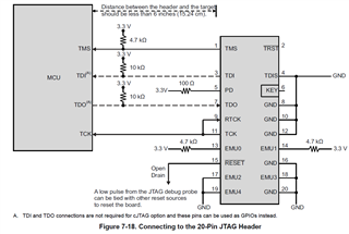
The series resistor on pin 5 (PD) has been decreased to 1.5Ohm in order to ensure 3.3V supply for the Blackhawk Isolation Adapter (they claim up to 80mA current draw from the target board, however it seems that both digital isolator ICs MAX14935 might consume around 40mA at 12.5MHz). Actually all the connections and auxiliary resistors that are depicted on Figure 7-18 above have been implemented on the target board harness (2-inches length) which is being further connected to the 20-pin on-board connector of the Blackhawk ISO110 adapter or to the TMDSEMU110-U Probe.
While we were trying to enter a debug session using the described setup with Code Composer Studio Version 11.0.0.00012 we ended up with an error message that the target is not supplied.
What has also been done and observed:
1. The Test Connection procedure in CCS has been successfully executed and both LEDs on the Isolation Adapter ISO110 board are iluminated twice. During the execution of the routine the TDI and TDO signals at the target side are monitored with an Oscilloscope and the MCU responds adequately.
2. The TMDSEMU110-U Debug Probe has been connected directly to the target board (without the Blackhawk Adapter) and it works faultlessly.
3. The JTAG Clock TCLK Frequency has been set to 2.5MHz, to 5.5MHz, then reduced to 100kHz.
4. Of cource in the Connection Properties in CCS the ISO 110 Isolation Adapter has been set to be supplied by the TMDSEMU110-U Probe and the Voltage has been selected to be 3.3V.
Also regarding the JTAG/SWD/cJTAG Mode property, it has been selected JTAG (1149.1).
It is presumed the following (not limited to):
A. Some of the pullup resistors that are mounted close to the target board connector (according to Figure 7-18. Connecting to the 20-pin JTAG header, SPRS945F) might not be needed or even they might need tods to be removed in case of using the Blackhawk ISO110 Adapter.
B. There might be some specific settings or limitations that are not revealed but must be implemented. Blackhawk company remains unreachable for support. And moreover the e2e forum has recommended to use the Blackhawk Isolation Adapter ISO110 therefore some people might had used this adapter and it is supposed to know all the application specifics.
So, please could you share some design thoughts about this case.
Best regards,
Cvetan Marinov


