This thread has been locked.

If you have a related question, please click the "Ask a related question" button in the top right corner. The newly created question will be automatically linked to this question.

TMS320F28377D: Random noise in ADC measurements

Part Number: TMS320F28377D
Other Parts Discussed in Thread: TMS320F28379D, LMV844, THS4531

We are using a F28377DPTPEP chip on our own PCB, and we are experiencing an issue with the ADC measurements.

The issue is that the ADC measurements have random noise in some samples when measuring signals around 1.5V.

To diagnose the problem:

  • We are measuring a constant signal of 1.5V.
  • We are using only SOC0 in the ADCD.
  • We are triggering measurements at constant intervals of around 300us.
  • We are triggering the measurements only by sw.
  • We are using a DAC to output the measured signal and compare the input and the output in real time with an oscilloscope.
    • The voltage in the input pin is perfectly constant as measured by the oscilloscope.
    • The DAC is not the problem since we tested a constant value and it works with perfect accuracy.

We have tested several sample and hold scale factors. In all of them the noise is similar.

We have also tested several resistances and capacitors in the input pin: With very small values the input signal is distorted, but with higher and mid values (currently 680Ohm, 100nF) the input signal is not distorted but the measurements are still noisy. Our circuit on the input is as follows: Voltage follower -> resistance -> input pin 56 (PTP format, ADCIND0) + capacitor to ground.

We believe this is not a hardware issue since we tested also on a LAUNCHPAD XL TMS320F28379D v2.0 and we are getting similar results.

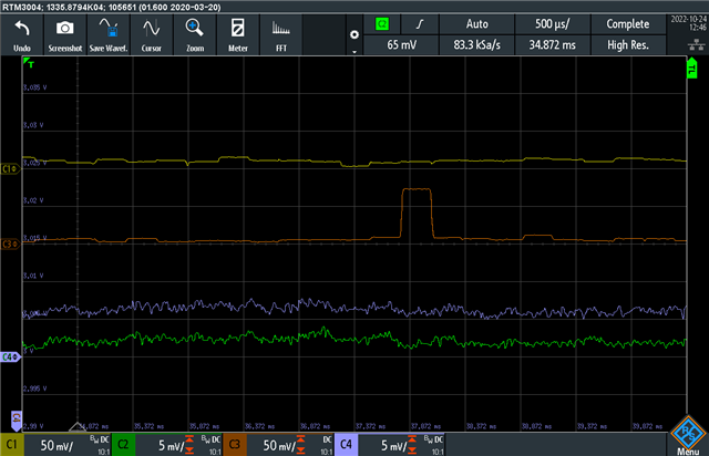
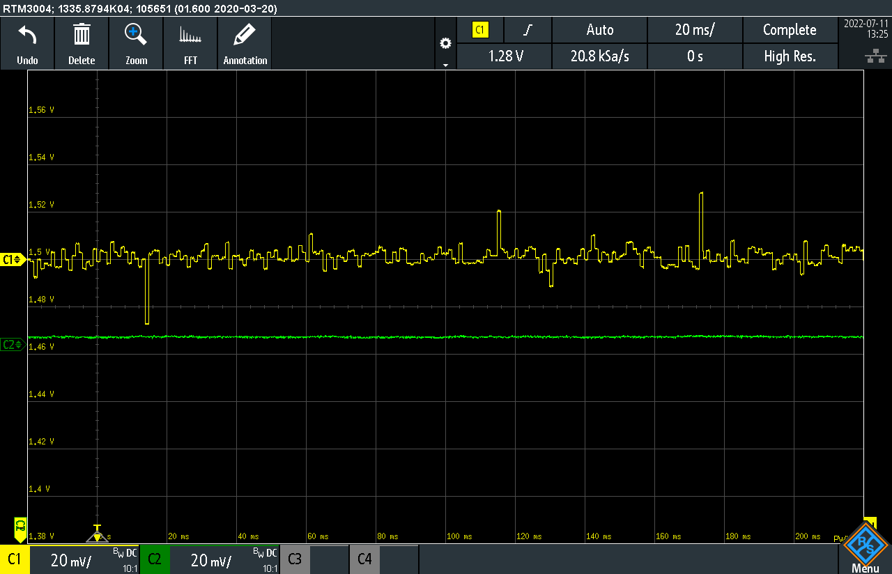
Below I include an image taken with the oscilloscope where C2 is the signal in the ADC input pin and C1 is the signal in the DAC output pin.
  • Anton,

    Can you comment if the ADC is in 16-bit mode or 12-bit mode for your setup?  I'm trying to correlate the noise you are seeing to a bit level of the ADC vs just raw voltage error.  It looks like +/-30mV from the scope plot.

    Can you also give the PN for the op-amp you are using for the voltage follower so I can look at its specs as well?

    Best,

    Matthew

  • Hello, Matthew,

    We are using 12-bit mode.

    The op-amp used for the voltage follower is an LMV844.

    Regards,

    Anton

  • Anton,

    Apologies for the delay on my side, I need a bit more time to look into this.  I will do my best to reply by tomorrow, the 15th.

    Best,

    Matthew

  • Anton,

    Are you using the internal or external reference for the ADC in your system.  If I recall correctly, for 12-bit mode we can use either internal or external; in the above case which ever reference you were using, can you switch to the other and see if that has any effect.

    Also, have you been able to read the ADC Result values and see the same behavior?  Understanding that bring this out through the BUFDAC is helpful in this case for debug, but I want to make sure we aren't dealing with some noise on BUFDAC vs ADC sample noise.

    Best,

    Matthew

  • Hello, Matthew,

    We are using external reference. I have reviewed the datasheet and I think it is not possible to use internal reference.

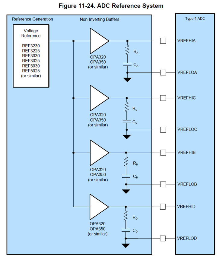
    The external reference circuit we are using is based on the one on the Technical Reference Manual (chapter 11.15.4 Designing an External Reference Circuit):

    We are using REF3030, LMV844, Rx = 0.1Ω and Cx = 22uF. VREFLOx directly to ground.

    In addition we have a 100nF capacitor to ground on the output of the REF3030.

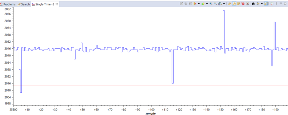
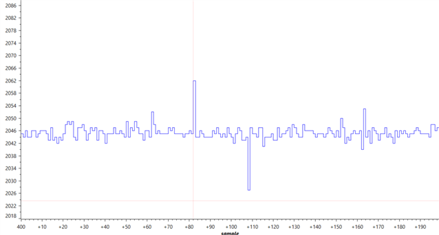
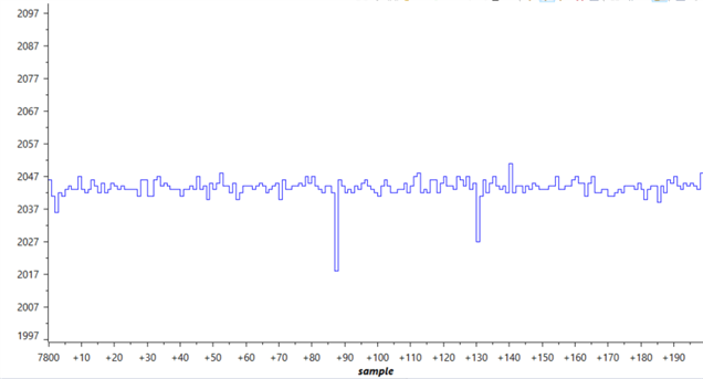
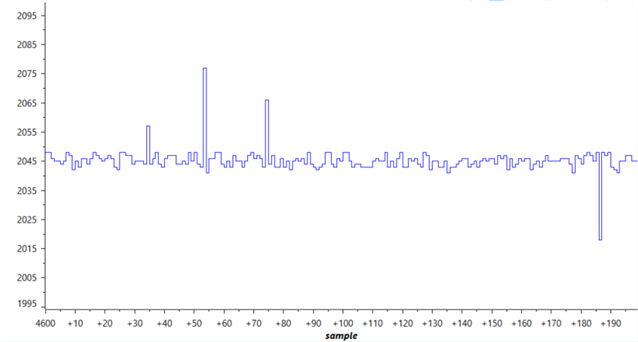
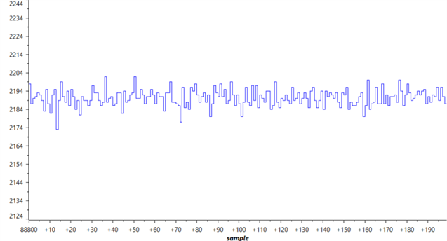
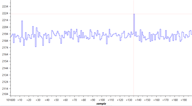
    By using debug mode we can see the same behavior on the ADC values. Below I attach an image taken from the debug graph in CCS.

    Regards,

    Anton

  • Hello, Matthew,

    Is it possible that the problem comes from something wrong in the configuration of the ADC?

    We are trying and we can't find anything that solves the issue.

    Regards,

    Anton

  • Anton,

    Can you share you ADC setup code, and if applicable how the ADC is triggered, i.e. PWM or SW, etc.  

    The code may answer the following, but are there multiple ADC active at the same time/sampling at the same time as the above channel?

    Best,

    Matthew

  • Hello, Matthew,

    We are triggering the ADC by SW, only SOC0 in ADCD.

    Here is the configuration code we are using for the ADC:

    void ConfigureADC(void)
    {
        EALLOW;
    
        /*
         * write configuration ADCIND
         */
        AdcdRegs.ADCCTL2.bit.PRESCALE = 6; //set ADCCLK divider to /4
        AdcSetMode(ADC_ADCD, ADC_RESOLUTION_12BIT, ADC_SIGNALMODE_SINGLE);
    
        //Set pulse positions to late
        AdcdRegs.ADCCTL1.bit.INTPULSEPOS = 1;
        //power up the ADCs
        AdcdRegs.ADCCTL1.bit.ADCPWDNZ = 1;
        //delay for 1ms to allow ADC time to power up
        DELAY_US(1000);
    
        //Select the channels to convert and end of conversion flag
        AdcdRegs.ADCSOC0CTL.bit.CHSEL = 0;  //SOC0 will convert pin D0
        AdcdRegs.ADCSOC0CTL.bit.ACQPS = 99; //sample window is 99 + 1 SYSCLK cycles (minimum 75ns)
    
        AdcdRegs.ADCINTSEL1N2.bit.INT2SEL = 0; //end of SOC0 will set INT2 flag
        AdcdRegs.ADCINTSEL1N2.bit.INT2E = 1;   //enable INT2 flag
        AdcdRegs.ADCINTFLGCLR.bit.ADCINT2 = 1; //make sure INT2 flag is cleared
    
        EDIS;
    }

    And here is the code for the measurement. This code is inside a cpu timer interrupt that runs every 200 us.

            // launch and measure channel Ir convert, wait for completion, and store results
            //start conversions immediately via software, ADCD
            AdcdRegs.ADCSOCFRC1.all = 0x0001; //SOC0
    
            //wait for ADCD to complete, then acknowledge flag
            while(AdcdRegs.ADCINTFLG.bit.ADCINT2 == 0);
            AdcdRegs.ADCINTFLGCLR.bit.ADCINT2 = 1;
    
            //store results
            ADCD0result = AdcdResultRegs.ADCRESULT0;
            DacbRegs.DACVALS.all=AdcdResultRegs.ADCRESULT0; // debugadc: adc measurement to dac

    Regards,

    Anton

  • Anton,

    I think the code looks OK, I'm still going through the sampling network.

    Would it be possible to change your code slightly to take 2 samples of the input signal back to back; i.e. set up ADCSOC1CTL exactly like you have set up ADCSOC0CTL. You want to move your ADC interrupt to SOC1.  Then write 0x0003 to the ADCSOCFRC1 register.  When the ISR comes use the ADCRESULT1 value and see if the noise remains?

    If you have enough buffer room, you could record both of them to compare ADCRESULT0/1 side by side.

    Best,

    Matthew

  • Hello, Matthew,

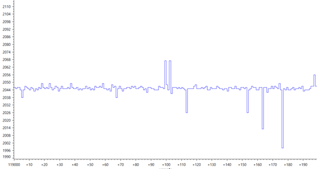
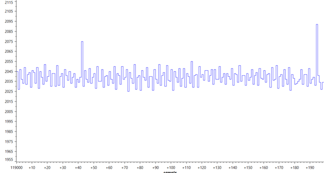
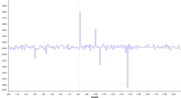
    I changed the code to take back to back measurements from SOC0 and SOC1 with the same constant value in both pins.

    The signal looks different but also noisy.

    These are the results taken at the same time:

    • SOC0:
    • SOC1:

    Regards,

    Antón

  • Hello, Matthew,

    I was checking the program again and I realized that in my previous post I was measuring two different pins connected to the same DC value in SOC0 and SOC1.

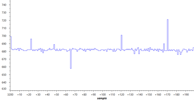
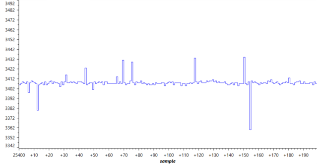
    I have changed the configuration to take measurements in SOC0 and SOC1 from the same input pin. Now the signals look more similar even though most noisy measurements are in different places. In the following images the samples on the same position of both graphs are taken back to back, and from one sample to the next there are 200us.

    SOC0:

    SOC1:

    Regards,

    Anton

  • Anton,

    Thanks for doing the experiment.  I don't think the issue is with settling time of the internal S/H cap since a double sample will typically help resolve those issues since the cap is "pre-charged" with the same value for the 2nd sample. 

    This also agrees with your earlier observation that changing the ACQPS doesn't seem to help.

    I'd like to see if this noise persists across different input voltages, would it be possible to change the force voltage to something in the 0.5V as well as 2.5V.  I want to get away from the center point of the converter to see if that changes anything noise wise.

    Also, I believe you mentioned changing the cap on the output of the op-amp; did you try changing the resistor as well?  680ohm is fairly large value; not sure if you have tried something smaller?

    Best,

    Matthew

  • Hello Matthew,

    Sorry for my delayed response.

    I have now tried with 0.5V and 2.5V, the results look very similar to the 1.5V regarding the noise.

    Here are some images for both cases:

    0.5V:

    2.5V:

    About the resistor, I recall having a smaller resistor in the first place and then changing it, but I can't remember exactly so we will do the test again.

    Regards,

    Anton

  • Hello Matthew,

    We changed the resistor on the output of the op-amp from 680ohm to 56ohm and the results are not good.

    We still have the random peaks, but now the baseline measurement are more noisy.

    Is there a possibility that triggering the measurements by HW istead of SW will solve the issue? Or is it completely unrelated? The project is at an advanced stage and this is holding it back so we are willing to try any possible solution.

    Regards,

    Anton

  • Anton,

    I'll need a few days to reply,  am out of office until Thursday.  I also want to add some others to the thread.   Will try my best to reply when I get back in the office. 

  • Hi Anton,

    Sincere apology for late response. Just wondering if you are looking for solution or thas been resolved?

    Thanks & Regards,

    Santosh

  • Hello Santosh,

    Thank you for getting back in touch.

    As a temporary solution we are taking 3 samples each time and using the median value. However, we are still looking to solve the issue to find a more convenient permanent solution.

    Regards,

    Anton

  • Hello PAk,

    No, I think it's different.

    In our case we have spikes (up or down) on individual samples. For what I can see on the video that feels more like noise that repeats periodically.

    Regards

  • Anton,

    Apologies for the lack of comms from the TI side on this one, we had been discussing internally but didn't reply.  Going back to the beginning there's only 2 sources of noise that this could be coming from; either from the main S/H cap on the channel of interest or if there is some perturbation of the external reference when you are converting.

    As you mention you also see this on the LaunchPad, which should take the reference circuit out of the equation since that's our design, etc.

    The amount of noise from your ADC result is ~40LSB or ~29mV, which as you pointed out we should be seeing on the input waveform/scope plot.

    The magnitude of the noise you see is independent on the pin level of analog input, and double sampling doesn't "filter" out this noise.

    Some more questions from me:

    • Confirm that any other ADC(A/B/C) are either not sampling, or if sampling they are coherent with the sample on ADC D above
      • If other ADCs are not in use, can you make sure they are disabled in SW to see if this has any effect
    • Would it be possible to scope the VREFHID/VREFLOD pins during the same conversions as above?
    • You had mentioned code use before, would it be possible to create a simple test that had minimal SW activity during the sample?
    • Kind of related to the above, is there any nearby(either pin or PCB trace) GPIO activity from the C2000?

    Best,

    Matthew

  • Hello Matthew,

    Regarding your questions:
    We are not using any of the other ADCs(A/B/C). Only ADCD.
    We are not configuring any ADC except ADCD. I don't know if there is a way to explicitly disable the other ADCs.

    Following your suggestions we have done the following tests:

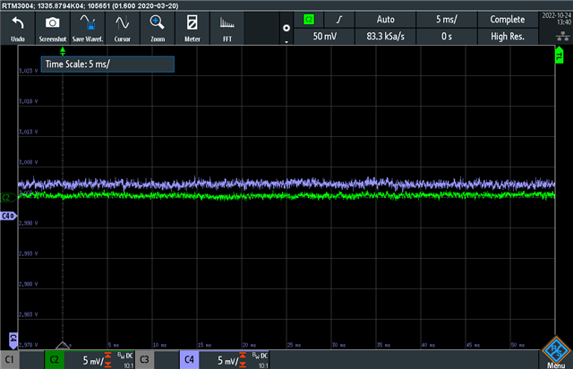
    Test 1. Disable all I/O activity except ADCD and 2 DACs. Comment most code unrelated to measurements. Use release mode and disconnect the debug cable from the computer. We are measuring:

    • ADCD0 (C1, yellow), connected to constant 1.5V
    • ADCD1 (C3, red), connected to constant 1.5V
    • VREFHID (C4, blue), around 3.005V
    • VREFLOD (C2, green) around 0.002V

    We can see the same spikes as always on the measurements on both ADCD0 and ADCD1.

    VREFHID and VREFLOD have low noise with some correlation between them as we can see on the zoomed scope.

    Test 2. Disable all I/O activity except ADCD. Comment most code unrelated to measurements. Use debug mode. We are measuring:

    • ADCD0, connected to constant 1.5V
    • ADCD1, connected to constant 1.5V
    • VREFHID (C4, blue), around 3.005V
    • VREFLOD (C2, green) around 0V

    The results are exactly like the previous test.

    We were using our own hardware in the previous tests. To start from the beggining, we have tested on the launchpad the example adc_ex1_soc_software provided with the C2000 SDK. The program has been modified only to take samples continuously and store them in an array. We have used a voltage divider between the built-in 3.3V and GND to create a constant voltage on the ADC pin.

    We are observing high levels of base noise but almost no spikes like in the other tests. Around 1 in 3000 measurements is very off the value, while in our hardware we are seeing around 1 bad measurement for every 100.
    Is this the behaviour we should be seeing in the LaunchPad with this example?

    Regards

  • Anton,

    As you mention the ADCIN derived form voltage bus will have some inherent noise supply coupled to it, making the ADC result have some baseline noise, but then we have the spikes still coming in as well.

    I'm looking at the pins in question a bit closer and want to verify some more aspects here:

    1)D0/D1 also share inputs with Comparator 7.  I want to make sure this is off(if you don't configure it at all, it shoud be off from reset)

    2)Can you change the code to use either A0/A1/B1 as the sampled channel, and then use the internal DAC to drive the voltage on the pin?  This should give us a known good reference to sample across both platforms

    3)I was going to suggest feeding the voltage into the THS4531, but I think #2 will accomplish what I want here without having to re-wire/route signals into that amp(it is a diff amp as well, so this would be a bit convoluted to sample SE).  Just wanted to articulate that in case it gave you any ideas

    4)We've been focused on VREFHI, if you could throw a scope on VDDA for one of the runs, just to confirm there is no odd spikes on the supply that would be good.  There is a DS defined condition that VREFHI cannot be greater than VDDA.  This shouldn't be the case on either board, but at least for the LP I know we are regulating the supply to 3.3V, so it shouldn't be happening there; but worth a check.

    5)I know we limited the digital activity, but wanted to make sure that XCLKOUT is not enabled somewhere in your code.

    Best,

    Matthew