


Part Number: TMS320F28374S
Dear Expert
Sorry to reply late,the original question is https://e2e.ti.com/support/microcontrollers/c2000-microcontrollers-group/c2000/f/c2000-microcontrollers-forum/1105330/tms320f28374s-tms320f28374s-startup-abnormal-problem-analysis-report?tisearch=e2e-sitesearch&keymatch=%20user%3A470630#
Problem description
1.Rf project 10 test debugging discovery part of the module dc control board DSP startup time is different, the individual module starts the charge of the power and then rereturns the electricity, and the long time DSP is required to work.
Second, problem analysis
To solve the problem of DSP startup, the project team analyzes the three sides:
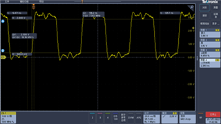
1.The external crystal oscillator of the signal;
In contrast to the normal start and abnormal launch of the DSP external crystal oscillator output, the output of the crystal oscillator is not different
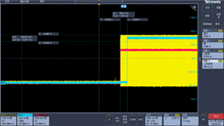
2.The electric sequence of the DSP on the DSP;
The electrical sequence on DSP is shown in figure 2. The # 1 channel is 3.3vc, # 2 channel for 1.2vc, # 3 channel as the vibration output. The time sequence is the external set 3.3v first power, the kernel 1.2v after the power, compared different modules, the time of the time is consistent, there is no significant difference.

The DSP reset signal sequence is shown in figure 3. The # 2 channel is the reset signal, the # 3 channel for the kernel 1.2v power supply signal. The reset signal is high when the electricity is about 136ms on 1.2v. Compare different difference modules, the reset signal is not different.
And this is the 20220720 reply:
1、Are you saying the startup time is different for multiple power-ups on the same board or are you saying the startup time is different across two (or more) boards, even though the design is identical?
A:The startup time is different for multiple power-ups on the same board.
2、Even though the above 3 points are true, there is still a difference in startup times. Is this correct?
A:YES.


