Dear TI members,
I am trying to implement a trip zone at only the zero crossings of an input ac voltage which is being sensed and read from an ADC. The PWM signals are forced to low using TZ if Vin (input ac voltage) is between -3<Vin<3 and it should then continue the regular PWM operation if Vin>3 or Vin<-3. For implementing this I have used the following code,
interrupt void adca1_isr(void)
{
random=random+1;
if(random==2048)
random=0;
Vin[2] = (0.1690*(AdcaResultRegs.ADCRESULT3)-348); // scaling the sensed voltage
if(Vin[2]>3)
{
d_eightA = 0;
d_eightB = 500;
dis=0;
}
if(Vin[2]<-3)
{
d_eightA = 500;
d_eightB = 0;
dis=0;
}
if((-3<=Vin[2])&&(Vin[2]<=3))
{
dis = 1;
EALLOW;
EPwm8Regs.TZCTL.bit.TZA = TZ_FORCE_LO;
EPwm8Regs.TZCTL.bit.TZB = TZ_FORCE_LO;
EDIS;
}
else
{
dis = 0;
}
EPwm8Regs.CMPA.bit.CMPA = d_eightA;
EPwm8Regs.CMPB.bit.CMPB = d_eightB;
AdcaRegs.ADCINTFLGCLR.bit.ADCINT1 = 1; //clear INT1 flag
PieCtrlRegs.PIEACK.all = PIEACK_GROUP1;
}
void ConfigureADC(void)
{
EALLOW;
//write configurations
//
AdcaRegs.ADCCTL2.bit.PRESCALE = 6; //set ADCCLK divider to /4
AdcSetMode(ADC_ADCA, ADC_RESOLUTION_12BIT, ADC_SIGNALMODE_SINGLE);
//
//Set pulse positions to late
//
AdcaRegs.ADCCTL1.bit.INTPULSEPOS = 1;
//
//power up the ADC
//
AdcaRegs.ADCCTL1.bit.ADCPWDNZ = 1;
//
//delay for 1ms to allow ADC time to power up
//
DELAY_US(1000);
EDIS;
}
void SetupADCEpwm(Uint16 channel)
{
Uint16 acqps;
//
//determine minimum acquisition window (in SYSCLKS) based on resolution
//
if(ADC_RESOLUTION_12BIT == AdcaRegs.ADCCTL2.bit.RESOLUTION)
{
acqps = 14; //75ns
}
else //resolution is 16-bit
{
acqps = 63; //320ns
}
//
//Select the channels to convert and end of conversion flag
//
EALLOW;
AdcaRegs.ADCSOC2CTL.bit.CHSEL = 2; //SOC3 will convert pin A3
AdcaRegs.ADCSOC2CTL.bit.ACQPS = acqps; //sample window is 100 SYSCLK cycles
AdcaRegs.ADCSOC2CTL.bit.TRIGSEL = 5; //trigger on ePWM1 SOCA/C
AdcaRegs.ADCINTSEL1N2.bit.INT1SEL = 3; //end of SOC0 will set INT1 flag
AdcaRegs.ADCINTSEL1N2.bit.INT1E = 1;
//AdcaRegs.ADCINTFLGCLR.bit.ADCINT1 = 1; //make sure INT1 flag is cleared
//AdcaRegs.ADCINTSEL1N2.bit.INT1CONT = 1; //enable INT1 flag
EDIS;
}
void InitEPwm8Example()
{
EPwm8Regs.TBPRD = 500; // Set timer period
EPwm8Regs.TBPHS.bit.TBPHS = 0; // Phase is 0
EPwm8Regs.TBCTL.bit.SYNCOSEL = TB_CTR_ZERO;
EPwm8Regs.TBCTR = 0x0000; // Clear counter
//
// Setup TBCLK
//
EPwm8Regs.TBCTL.bit.CTRMODE = TB_COUNT_UPDOWN; // Count up
EPwm8Regs.TBCTL.bit.PHSEN = TB_DISABLE; // Disable phase loading
EPwm8Regs.TBCTL.bit.HSPCLKDIV = TB_DIV1; // Clock ratio to SYSCLKOUT
EPwm8Regs.TBCTL.bit.CLKDIV = TB_DIV1;
EPwm8Regs.CMPCTL.bit.SHDWAMODE = CC_SHADOW; // Load registers every ZERO
EPwm8Regs.CMPCTL.bit.SHDWBMODE = CC_SHADOW;
EPwm8Regs.CMPCTL.bit.LOADAMODE = CC_CTR_ZERO;
EPwm8Regs.CMPCTL.bit.LOADBMODE = CC_CTR_ZERO;
EPwm8Regs.AQCTLA.bit.CAD = AQ_CLEAR; // Set PWM1A on Zero
EPwm8Regs.AQCTLA.bit.CAU= AQ_SET;
EPwm8Regs.AQCTLB.bit.CBD = AQ_CLEAR; // Set PWM1A on Zero
EPwm8Regs.AQCTLB.bit.CBU = AQ_SET;
}
interrupt void reset_isr(void)
{
EALLOW;
if (dis == 1)
EPwm8Regs.TZFRC.bit.CBC = 1;
else
EPwm8Regs.TZCLR.bit.CBC = 1;
EDIS;
}
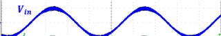
The above code that I used makes all the ePWM signals low but it is unable to make them run in normal operation when Vin goes greater than 3V or less than -3V. The desired PWM should be something like this,