This thread has been locked.

If you have a related question, please click the "Ask a related question" button in the top right corner. The newly created question will be automatically linked to this question.

TMS320F280049C: Sensored_FOC

Part Number: TMS320F280049C
Other Parts Discussed in Thread: C2000WARE, TMDSHVMTRINSPIN

Hi Team,

we are Working on sensor Based FOC using TMS320F280049C.

I am using Example project path:  C:\ti\c2000\C2000Ware_MotorControl_SDK_<version>\solutions\universal_motorcontrol_lab\f28002x.

I am following ti document " https://www.ti.com/lit/spruj26".

I Changed driverlib files, hal.c, user.h, etc. of f28002x to f28004x Micro controller. Present I am checking PWM's by using level1 Incremental Build Procedure

My problem is, 1) ISR count is not Updated as per Document procedure. I Don't Know  Where it can be Incremented in main code.

2). I am not getting DC Bus Voltage.

Please Help me to solve this issue.

  • Is motor1CtrlISR (in motor1_drive.c) not executing? How did you configure the interrupt related #defines (MTR1_ADC_INT_BASE, MTR1_ADC_INT_NUM, etc...) in hal.h? Does the SOC happen to be the same one you use for the DC bus voltage?

    F28002x and F28004x have different numbers of ADC instances. Did you miss adding the third instance to the adcHandle or adcResult arrays in hal_obj.h? Did you miss anything in HAL_init or HAL_setupADCs?

    Whitney

  • First of all Thank You.,
    I Have one Doubt, While Porting code from f28002x to f28004 How to Change Memory map File after Importing Project?

    "Import the "universal_motorcontrol_lab_f28004x" project into CCS, open the "f28004x_flash_lib_is_eabi.cmd" file to change the memory map according to the used F28004x device".

    Please Give me suggestion how to change memory map of f28002x to f28004x Device.

  • Thank You for Your help.

    I followed the above Thread. Now, I need to clarify on f28004x Memory map File.

    Memory Allocation is Different for f28002x and f28004x.(Ex: Bank 0, Bank 1 in f28004x) How can I Assign Memory allocation for  f28004x device?

    Below is the present Existed cmd file "f28002x_flash_lib_is_eabi.cmd".

    I Need Memory Mapping file for "f28004x_flash_lib_is_eabi.cmd".

    /*
    // FILE:    f28002x_flash_lib_is_eabi.cmd
    //
    // TITLE:   Linker Command File For F280025 examples that run out of Flash
    //
    //
    //          Keep in mind that L4, L5,L6 and L7 are protected by the code
    //          security module.
    //
    //          What this means is in most cases you will want to move to
    //          another memory map file which has more memory defined.
    //
    */
    
    MEMORY
    {
       BEGIN           	  : origin = 0x00080000, length = 0x00000002
       BOOT_RSVD	      : origin = 0x00000002, length = 0x00000126
    
    /* RAMLS5        	  : origin = 0x0000A800, length = 0x00000800 */
    /* RAMLS6    		  : origin = 0x0000B000, length = 0x00000800 */
    /* RAMLS7        	  : origin = 0x0000B800, length = 0x00000800 */
       RAMLS567    		  : origin = 0x0000A600, length = 0x00001A00
    
       /* Flash sectors */
       /* BANK 0 */
    /* FLASHBANK0_SECT0	  : origin = 0x00080002, length = 0x00000FFE */
       FLASHBANK0_BOOT	  : origin = 0x00080002, length = 0x00000FFE	/* remote update */
    /* FLASHBANK0_SECT1	  : origin = 0x00081000, length = 0x00001000 */
    /* FLASHBANK0_SECT2	  : origin = 0x00082000, length = 0x00001000 */
    /* FLASHBANK0_SECT3	  : origin = 0x00083000, length = 0x00001000 */
    /* FLASHBANK0_SECT4	  : origin = 0x00084000, length = 0x00001000 */
    /* FLASHBANK0_SECT5	  : origin = 0x00085000, length = 0x00001000 */
    /* FLASHBANK0_SECT6	  : origin = 0x00086000, length = 0x00001000 */
    /* FLASHBANK0_SECT7	  : origin = 0x00087000, length = 0x00001000 */
    /* FLASHBANK0_SECT8	  : origin = 0x00088000, length = 0x00001000 */
    /* FLASHBANK0_SECT9	  : origin = 0x00089000, length = 0x00001000 */
    /* FLASHBANK0_SECT10  : origin = 0x0008A000, length = 0x00001000 */
    /* FLASHBANK0_SECT11  : origin = 0x0008B000, length = 0x00001000 */
    /* FLASHBANK0_SECT12  : origin = 0x0008C000, length = 0x00001000 */
    /* FLASHBANK0_SECT13  : origin = 0x0008D000, length = 0x00001000 */
       FLASHBANK0_CODE	  : origin = 0x00081000, length = 0x0000D000	/* control code */
    
    /* FLASHBANK0_SECT14  : origin = 0x0008E000, length = 0x00001000 */
       FLASHBANK0_DATA 	  : origin = 0x0008E000, length = 0x00001000	/* constant data */
    
       FLASHBANK0_SECT15  : origin = 0x0008F000, length = 0x000FF0
       FLASHBANK0_SEC15_RSVD	: origin = 0x08FFF0, length = 0x000010  /* Reserve and do not use for code as per the errata advisory "Memory: Prefetching Beyond Valid Memory" */
    
       BOOTROM			  : origin = 0x003F0000, length = 0x00008000
       BOOTROM_EXT		  : origin = 0x003F8000, length = 0x00007FC0
       RESET           	  : origin = 0x003FFFC0, length = 0x00000002
    
       RAMM0S          	  : origin = 0x00000128, length = 0x00000118	/* stack, on-chip RAM block M0 part */
       RAMM1D         	  : origin = 0x00000240, length = 0x000005B8	/* on-chip RAM block M0 part & M1 */
       RAMM1_RSVD         : origin = 0x000007F8, length = 0x00000008    /* Reserve and do not use for code as per the errata advisory "Memory: Prefetching Beyond Valid Memory" */
    
       RAMGS0     	   	  : origin = 0x0000C000, length = 0x000007F8
       RAMGS0_RSVD        : origin = 0x0000C7F8, length = 0x00000008    /* Reserve and do not use for code as per the errata advisory "Memory: Prefetching Beyond Valid Memory" */
    
       RAMLS4        	  : origin = 0x0000A000, length = 0x00000600
    }
    
    
    SECTIONS
    {
       .reset           : > RESET, 				   	TYPE = DSECT
       codestart		: > BEGIN,     		 	   	ALIGN(4)
    
    
       GROUP
       {
    #if defined(SFRA_ENABLE)
           .TI.ramfunc
           {
             -l sfra_f32_tmu_eabi.lib<sfra_f32_tmu_collect.obj> (.text)
             -l sfra_f32_tmu_eabi.lib<sfra_f32_tmu_inject.obj> (.text)
           }
    #else
    	   .TI.ramfunc
    #endif
           ramfuncs
           	/* Digital Controller Library functions */
           dclfuncs
           dcl32funcs
       }          LOAD = FLASHBANK0_CODE
                  RUN = RAMLS567,
                  LOAD_START(RamfuncsLoadStart),
                  LOAD_SIZE(RamfuncsLoadSize),
                  LOAD_END(RamfuncsLoadEnd),
                  RUN_START(RamfuncsRunStart),
                  RUN_SIZE(RamfuncsRunSize),
                  RUN_END(RamfuncsRunEnd),
                  ALIGN(2)
    
    	ctrlfuncs : {
    	            }
    	          LOAD = FLASHBANK0_CODE
                  RUN = RAMLS567,
                  LOAD_START(ctrlfuncsLoadStart),
                  LOAD_SIZE(ctrlfuncsLoadSize),
                  LOAD_END(ctrlfuncsLoadEnd),
                  RUN_START(ctrlfuncsRunStart),
                  RUN_SIZE(ctrlfuncsRunSize),
                  RUN_END(ctrlfuncsRunEnd),
                  ALIGN(2)
    
       .text            : > FLASHBANK0_CODE,	ALIGN(8)
       .cinit           : > FLASHBANK0_CODE,	ALIGN(4)
       .switch          : > FLASHBANK0_CODE,	ALIGN(4)
       .cio				: > FLASHBANK0_CODE
       .pinit           : > FLASHBANK0_CODE,	ALIGN(4)
       .const           : > FLASHBANK0_CODE,  	ALIGN(4)
       .init_array      : > FLASHBANK0_CODE, 	ALIGN(4)
    
       .stack           : > RAMM0S
       .bss             : > RAMM1D
       .bss:output      : > RAMM1D
       .bss:cio         : > RAMM1D
       .data            : > RAMM1D
       .sysmem          : > RAMM1D
    
         est_data             	 : > RAMLS4
    }
    
    SECTIONS
    {
       prms_data 		      : > FLASHBANK0_DATA
    
       GROUP
       {
          user_data
    	  foc_data
       }
       		LOAD = RAMM1D
            LOAD_START(ctrlVarsLoadStart),
            LOAD_SIZE(ctrlVarsLoadSize),
            LOAD_END(ctrlVarsLoadEnd)
    
       GROUP
       {
          sys_data
          ctrl_data
          motor_data
       }
            LOAD = RAMGS0
            LOAD_START(motorVarsLoadStart),
            LOAD_SIZE(motorVarsLoadSize),
            LOAD_END(motorVarsLoadEnd)
    
    
       GROUP
       {
    	  vibc_data
    	  dmaBuf_data
    
          datalog_data
          graph_data
    
          sfra_data
          SFRA_F32_Data
       }
            LOAD = RAMGS0
            LOAD_START(extVarsLoadStart),
            LOAD_SIZE(extVarsLoadSize),
            LOAD_END(extVarsLoadEnd)
    }
    /*
    //===========================================================================
    // End of file.
    //===========================================================================
    */
    

  • I think instead of copying the f28002x_flash_lib_is_eabi.cmd and changing it to support F28004x, it might be easier to take an existing F28004x cmd file and add the additional sections (user_data, foc_data, sys_data, etc...) to that.

    I think this one you can find in C2000Ware might be a good starting point: c2000ware\device_support\f28004x\common\cmd\28004x_generic_flash_link.cmd

    These are some helpful articles if you need some guidance about how linker files work:

    https://software-dl.ti.com/ccs/esd/documents/sdto_cgt_Linker-Command-File-Primer.html

    https://software-dl.ti.com/ccs/esd/documents/c2000_c28x-compiler-understanding-linking.html

    Whitney

  • Thank You "Whitney Dewey".

    c2000ware\device_support\f28004x\common\cmd\28004x_generic_flash_link.cmd.

    1.I followed as you said, But it Showing the Errors. Please Give me a Suggestion to solve this.

    2.in place of "f28004x_flash_lib_is_eabi.cmd" file, I am using "f28002x_flash_lib_is_eabi.cmd" this File. Code Working Properly. But I am not getting ADC Readings Every Time. (Only Power on time am getting ADC Values in Registers).

    Now My Point is, is there any Relation between memory mapping and ADC readings in main Code.

    Please reply me as soon as Possible.
    Thank You.

  • 1. Can you tell me what errors you're seeing? I should be able to help you figure out what edits you need to make to the cmd file to resolve them.

    2. If you look at the ADC result registers are they not updating? If the ADC registers themselves aren't updating, it's probably an ADC or PWM issue rather than an RAM issue. Or are the result registers updating but variable where we store them not updating? Can you confirm that the ISR is executing?

    Whitney

  • 2. If you look at the ADC result registers are they not updating? If the ADC registers themselves aren't updating, it's probably an ADC or PWM issue rather than an RAM issue. Or are the result registers updating but variable where we store them not updating? Can you confirm that the ISR is executing?

    ISR is Executing. Because ISR Count Is Incrementing. Getting PWM's Also With 120 Degree Phase Shift.

    Then I don't know y ADC Readings are not Updated on Every Time(Only Updated in Power on condition).

    can You Guess what Mistake Happened to this Problem.

  • Again, just to clarify--both the ADC result variables (motorVars_M1.adcData) and the ADC result registers (as viewed in the CCS registers view) are both failing to update?

    It sounds like your PWMs are working, but maybe something went wrong with the SOCA event setup. Did you make any changes to MTR1_ADC_TRIGGER_SOC in hal.h? Or changes to the HAL_setupPWMs() function?

    Whitney

  • I Changed ADC SOC In hal.h Because In f28004x device does not Support To C6 Channel. So I Changed ADC Channels That's It.

    In Watch Expression Window I Observed, Some Time Failed To Update and Some Time Updating.

  • Are you using ADC B at all (which doesn't exist on F28002x but does exist on F28004x) or have you been able to stick to just using A and C like the F28002x code? Are you using a TI EVM or are you using custom hardware?

    In Watch Expression Window I Observed, Some Time Failed To Update and Some Time Updating.

    How are you checking them? Are you putting a breakpoint somewhere in the code and watching the ADC results change each time the breakpoint hits? Or just letting the code run and watching the expressions window with continuous refresh turned on?

    Are there only specific channels that are failing to update or all of them?

    Whitney

  • Hi,

    "Are you using ADC B at all (which doesn't exist on F28002x but does exist on F28004x) or have you been able to stick to just using A and C like the F28002x code? Are you using a TI EVM or are you using custom hardware?"

    I am Using TI Kit (f28004x Device) Only.

    I am using ADC C Registers but Channels are Changed from C6 to C5. I am Attaching My ADC definitions below, Please Check it Once.

  • "How are you checking them? Are you putting a breakpoint somewhere in the code and watching the ADC results change each time the breakpoint hits? Or just letting the code run and watching the expressions window with continuous refresh turned on?

    Are there only specific channels that are failing to update or all of them?".

    1.I am checking them on just letting the code run and watching the expressions window with continuous refresh turned on. I am Checking ADC Registers Also, both were not updated.

    2.not specific channels, Failed to update whole ADC Module results.

    3. How can I Solve This issue?

    Please help me.

  • I am Using TI Kit (f28004x Device) Only.

    Are you using the F28004x board (LaunchPad or controlCARD) with another motor control board? Like TMDSHVMTRINSPIN? Or one of our DRV83xx boards? If I know the exact board combination you're using, I can help double check the channel mappings. Or are you just testing it with the F28004x EVM board alone with nothing attached?

    Whitney

  • 1.I am checking them on just letting the code run and watching the expressions window with continuous refresh turned on. I am Checking ADC Registers Also, both were not updated.

    Can you also try testing using breakpoints? Maybe point a breakpoint in the ISR on the line after HAL_readMtr1ADCData() is called and see if adcData updates from breakpoint to breakpoint, just in case the continuous refresh isn't working for some reason.

    Whitney

  • breakpoint in the ISR on the line after HAL_readMtr1ADCData() Is Not Working. While Putting Breakpoint at This Function automatically Disabled My Break Point.

    I Am Putting Breakpoint At Isrcount, It's Working. In My Code Everywhere Breakpoint Working Except Adc Functions.

    Can You Help Me To Solve this Issue?

  • That might be because of the optimization level. I think the HAL_readMtr1ADCData function is inlined, so it's not actually a function call when optimization is turned on. CCS may be having trouble determining where to place the breakpoint because of that.

    It doesn't necessarily have to be the very next line after HAL_readMtr1ADCData  is called. Anywhere shortly after that call should be okay. You could also try temporarily turning off optimization in your project properties and see if that allows you to place breakpoints more easily.

    Whitney

  •  Why My Offset_I_ad 131.42 Coming, From Universal Lab Control Manual Offsets Are Near To 2048 Count. Those Are Not Updated Now.
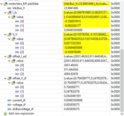
    Can You Check It once. please Update Me

  • Your VdcBus is nearly zero. Are you sure you've selected the right ADC channel for that signal? I asked before--could you tell me what inverter EVM are you using so I can check the channel mapping? Did you power it on?

    Whitney

  • I am Checking without connecting HVKIT. That's why VDC bus is nearly ZERO. "Because ADC readings are not updated in every time" I already told to U. so, I am Debugging code with f28004x Launchpad only. If its Working Here then I will Test with HVKIT.

    Again I am Asking Question for Clarity,

    1.ADC Readings are Updating in Some times.

    2.After that am not getting ADC Readings in Watch Expressions as well as Registers(ADC Result registers).Second time flashing same code with same Device, why its not working?

    Why It's Working Some times and Sometimes not working? Can You Verify it?.

    Waiting for your update.

    Thank you.

  • So you've selected C0-5 as your ADC channels for now for testing with the LP, but will replace them with the correct channels for the F28004x+100DIM+HVKIT later?

    The main reason the ADC would stop updating results would be if it stopped receiving the trigger signal, but you're able to see that the PWMs are working and the fact that the ISR keeps executing means that ADC conversions are finishing. If you look at the ADC registers in the Registers view, they appear as expected? No overflow flags set or configurations corrupted?

    You don't have those ADC pins connected to anything? If you jumper the corresponding pin to 3.3V on the LaunchPad, you see no reaction in adcData in the Expressions window?

    Whitney

  • "You don't have those ADC pins connected to anything? If you jumper the corresponding pin to 3.3V on the LaunchPad, you see no reaction in adcData in the Expressions window?"

    I am connecting those adc channels to 3.3V on Launch pad. am checking in expression window.

    Now I Have Some Improvement than Previous Tests. Can You Verify it once.

    Please Check it Once and give Updates what I have Missed in it?

  • You can take a look at the the runMotor1OffsetsCalculation() function to see where the offsets come from. The offset calculation isn't really going to work without having an inverter board connected, so it makes sense that you wouldn't see offsets that match what you see in the universal lab.

    I think as long as you're able to use a jumper wire to toggle each ADC pin between 3.3V and ground to verify that the correct result register and variable is changing while the code is running, you can be reasonably confident that the ADC is working. Are you able to confirm that?

    Whitney

  • Hi Whitney dewey,

    I am Getting ADC Readings. Can you Verify My ADC data is correct or Not?

    I am Using TMS320f280049C + HVKIT, Below are Offset ADC's.

    Please Verify it once.

    Thanks and Regards.

  • I assume you just had the +15V supply for the IPM gate driver connected for now? These results look as expected to me.

    Whitney

  • Hi,

    Thanks For the Reply.

    Yes, I just had the +15V Supply for the IPM gate driver connected.

    I Have below doubts on ADC reading 

    1. Why SOC linked with Post-Processing Block(PPB) For Current Readings ?

    2 .In the watch window expressions current values (motorVars_M1.adcData >> I_A as shown in below image) are updating continuously w.r.t. ADC counts, but we observed that voltage values (motorVars_M1.adcData >> V_V shown in below image) are not updating consciously (Updating randomly).  


    3.We are going to run PMSM motor with HV -KIT in Build level 2, what are the precautions I need to take? (I am following the Universal Lab User Manual)

    FYI: We enabled FAST in the predefined symbols. 

  • The PPB is being used to subtract the offset from the current conversion. Basically the hardware does the subtraction for you so you don't have to spend the additional cycles in your ISR doing it in software.

    Have you looked at the solutions\tmdshvmtrinspin\ example for F28004x? There are some guides in the docs folder that may be helpful for hardware setup. You could also take a look at the HAL files to double check that the ADC channel assignments you used in your port of the universal lab match. It doesn't use the PPB, but you could still use it to check that the channels and SOCs you selected look good.

    Whitney

  • Thanks For the Reply.

    Now, I understood Why SOC linked with PPB.

    2 .In the watch window expressions current values (motorVars_M1.adcData >> I_A as shown in below image) are updating continuously w.r.t. ADC counts, but we observed that voltage values (motorVars_M1.adcData >> V_V shown in below image) are not updating consciously (Updating randomly). 

    Can You Explain The Second Question?

  • Hi Whitney Dewey,

    1.After Porting the code from f28002x device to f28004x device, I am changing ADC and PWM Configuration w.r.t. HVKIT(as shown in below Image).

    2.I have changed the Motor Parameters w.r.t. TI PMSM motor.

    3.I have changed the remaining GPIOs w.r.t. f28004X Device.

    4.Now, We are going to run PMSM motor with HV -KIT in Build level 2 (i.e. Open loop). I am following the TI document " https://www.ti.com/lit/spruj26" (as reference). We are familiar with HVKIT connections. 

    I Request You to give the confirmation on above steps to run the motor.

  • Your ADC settings look good to me. Did you also update the CMPSS and EPWM XBAR for the overcurrent fault trip?

    Whitney

  • Thank You for reply.

    yes I have Updated the CMPSS and EPWM XBAR for the overcurrent fault trip.

  • Hi Whitney Dewey,

    Thanks for the reply,

    1.I have changed the code to 280049C as informed in the above posts

    2. “Now, We are going to run PMSM motor with HV -KIT in Build level 2 (i.e. Open loop). I am following the TI document " https://www.ti.com/lit/spruj26" (as reference). We are familiar with HVKIT connections. 

    I Request You to give the confirmation on above steps to run the motor “ Can you please confirm the above?

  • The lab guide instructions are still applicable for the F28004x. SPRUJ26 is the correct doc to follow, yes.

    Whitney