Part Number: TMS320F28384D
Other Parts Discussed in Thread: LAUNCHXL-F28379D, C2000WARE
Dear Team,
we have created a project using SPIA_BASE with respected PIns
58 - SIMO
59 - SOMI
60 - CLK
61 - GPIO_FOR CS
to communicate and store data to an EEPROM IC CAT25128 using LAUNCHXL-F28379Dlaunchpad and it works.
But when i tried to port it to SPIB_BASE on our customer required custom board TMS320F28384D THE TX DATA AND RX DATA IS MISS MATCHED. what are we doing wrong.
/////////////////////////////////////////////////////////////////////////////////////////////////////////////////////////////////////////////////////////////////////////////////////////////////////////////////////////////////////////////////////////////////////////////////////////////////////////////////////////////////
FOR LAUNCHXL-F28379Dlaunchpad.
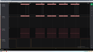
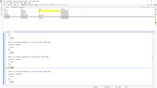
below image: while reading EEPROM Status register. and the spi is configured to 4 bitrate. in launchpad.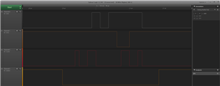
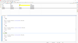
below image: writing data to eeprom through spia base from launch pad.and the spi is configured to 4 bitrate
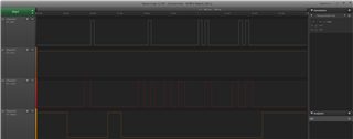
below image: Reading data to eeprom through spia base from launch pad.and the spi is configured to 4 bitrate
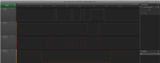
below are the pin mux, SPIA_BASE configuration and send and receive function used in LAUNCHXL-F28379D launchpad.
uint16_t spitxrx(uint16_t data){
uint32_t base = SPIA_BASE;
uint16_t z, RX;
z = data << 8;
z &= 0xff00;
while((HWREGH(base + SPI_O_STS) & SPI_STS_BUFFULL_FLAG) != 0U);
HWREGH(base + SPI_O_TXBUF) = z;
while((HWREGH(base + SPI_O_STS) & SPI_STS_INT_FLAG) == 0U);
RX = (HWREGH(base + SPI_O_RXBUF));
return(RX);
}
void PinMux_init()
{
GPIO_setPinConfig(GPIO_58_SPISIMOA);
GPIO_setPadConfig(58, GPIO_PIN_TYPE_PULLUP);
GPIO_setQualificationMode(58, GPIO_QUAL_ASYNC);
GPIO_setPinConfig(GPIO_59_SPISOMIA);
GPIO_setPadConfig(59, GPIO_PIN_TYPE_PULLUP);
GPIO_setQualificationMode(59, GPIO_QUAL_ASYNC);
GPIO_setPinConfig(GPIO_60_SPICLKA);
GPIO_setPadConfig(60, GPIO_PIN_TYPE_PULLUP);
GPIO_setQualificationMode(60, GPIO_QUAL_ASYNC);
GPIO_setPinConfig(GPIO_61_GPIO61);
GPIO_setPadConfig(61, GPIO_PIN_TYPE_STD);
GPIO_setDirectionMode(61, GPIO_DIR_MODE_OUT);
}
void SPI_init()
{
SPI_disableModule(SPIA_BASE);
SPI_setConfig(SPIA_BASE, DEVICE_LSPCLK_FREQ, SPI_PROT_POL0PHA1,
SPI_MODE_MASTER, 10000000, 8); ////// bitrate set to 4.
SPI_disableFIFO(SPIA_BASE);
SPI_disableLoopback(SPIA_BASE);
SPI_setEmulationMode(SPIA_BASE, SPI_EMULATION_FREE_RUN);
SPI_enableModule(SPIA_BASE);
}
//////////////////////////////////////////////////////////////////////////////////////////////////////////////////////////////////////////////////////////////////////////////////////////////////////////////////////////////////////////////////////////////////////////////////////////////////////////////////////////////
//////////////////////////////////////////////////////////////////////////////////////////////////////////////////////////////////////////////////////////////////////////////////////////////////////////////////////////////////////////////////////////////////////////////////////////////////////////////////////////////
FOR CUSTOM BOARD-F28384D.
our custom board uses a 20MHZ external oscillator. and the available spi pins are 24,25,26,27. we configrued the LSPCLK to be divided by 1. and set the LSPCLK prescaler to 1.
24 - SIMO
25 - SOMI
26 - CLK
27 - GPIO for CS
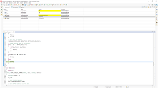
Below image: While reading EEPROM status register. using custom board. bitrate set to 4
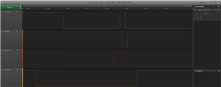
Below image: while writing Data to EEPROM with custom board . bitrate set to 4.
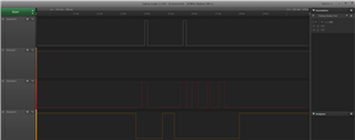
Below image: While reading data from EEPROM Address with custom board. bitrate set to 4. YOU CAN SEE THAT THE EEPROM IS SENDING DATA BUT IT IS MISS MATCHED.
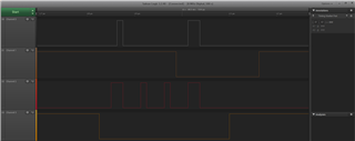
The Below are the pin mux and spi base configuration and function used to send and recive data
uint16_t spitxrx(uint16_t data){ //function to send and recive data.
uint32_t base = SPIB_BASE;
uint16_t z, RX;
z = data << 8;
z &= 0xff00;
while((HWREGH(base + SPI_O_STS) & SPI_STS_BUFFULL_FLAG) != 0U);
HWREGH(base + SPI_O_TXBUF) = z;
while((HWREGH(base + SPI_O_STS) & SPI_STS_INT_FLAG) == 0U);
RX = (HWREGH(base + SPI_O_RXBUF));
return(RX);
}
void PinMux_init()
{
//
// SPIB -> mySPI0 Pinmux
//
GPIO_setMasterCore(24, GPIO_CORE_CPU1);
GPIO_setPinConfig(GPIO_24_SPIB_SIMO);
GPIO_setPadConfig(24, GPIO_PIN_TYPE_PULLUP);
GPIO_setQualificationMode(24, GPIO_QUAL_ASYNC);
GPIO_setMasterCore(25, GPIO_CORE_CPU1);
GPIO_setPinConfig(GPIO_25_SPIB_SOMI);
GPIO_setPadConfig(25, GPIO_PIN_TYPE_PULLUP);
GPIO_setQualificationMode(25, GPIO_QUAL_ASYNC);
GPIO_setMasterCore(26, GPIO_CORE_CPU1);
GPIO_setPinConfig(GPIO_26_SPIB_CLK);
GPIO_setPadConfig(26, GPIO_PIN_TYPE_PULLUP);
GPIO_setQualificationMode(26, GPIO_QUAL_ASYNC);
// GPIO27 -> SPI_CS_GPIO Pinmux
GPIO_setMasterCore(27, GPIO_CORE_CPU1);
GPIO_setPinConfig(GPIO_27_GPIO27);
GPIO_setPadConfig(27, GPIO_PIN_TYPE_STD);
GPIO_setDirectionMode(27, GPIO_DIR_MODE_OUT);
}
void SPI_init() //same as which i used in launch pad f28379d except for base and pins.
{
//mySPI0 initialization
SPI_disableModule(SPIB_BASE);
SPI_setConfig(SPIB_BASE, DEVICE_LSPCLK_FREQ, SPI_PROT_POL0PHA1,
SPI_MODE_MASTER, 40000000, 8); ///bitrate set to 4.
SPI_disableFIFO(SPIB_BASE);
SPI_disableLoopback(SPIB_BASE);
SPI_setEmulationMode(SPIB_BASE, SPI_EMULATION_FREE_RUN);
SPI_enableModule(SPIB_BASE);
}