This thread has been locked.

If you have a related question, please click the "Ask a related question" button in the top right corner. The newly created question will be automatically linked to this question.

TMS320F28335: Maximum Output current

Part Number: TMS320F28335

Hi Champ,

From data sheet the group 2 IO maximum output current are +/-8mA.

customer  outside circuit is RC:  R is 100OHM, C is 1uF.

the current waveform when  F28335 IO output 3.3V like following:

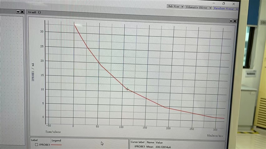
The current will drop from 33mA to 8mA with in 150uS, may i know this case will lead the PIN be damaged or not?

  • Hello Huihuang,

    From what I'm understanding, you're saying that the current on the pin drops from 33 mA to 8 mA within 150 us. If this is the case, I do not know how long it will take for a high current to damage the pin, but we cannot guarantee that the device will operate properly or remain undamaged. I will ask another expert to confirm, but from my understanding of this case, it may or may not work but we cannot guarantee there will be no damage occurring.

    Best regards,

    Omer Amir

  • Amir,

    I think the maximum current is  constant current, so need you help customer case that  the current on the pin drops from 33 mA to 8 mA within 150 us have issue or not.

  • Hello Huihuang,

    I contacted another expert to confirm and this is what they stated:

    "The Absolute Maximum Ratings table is one key table to look at here.  We have 20mA max limit which should not be exceeded at any time.  From the plot, the 33mA peak would be a problem.

    For continuous operation the 8mA limit should be observed.  This could be a DC rating (resistive load), or RMS current (for capacitive loads like this if switching is at high frequency)."

    I hope this helps clarify.

    Best regards,

    Omer Amir

  • Hello Amir,

    Customer still have concern about this RMS current , for example, for the PWM output pin , usually will connect RC filter, for example, R is 100ohm, C is 0.1uF, when the PWM output high level, the capacitor will be charged, and the maximum current will be 30mA.  if the maximum is just 20mA, then customer application will always has issue.

  • Hi Huihuang,

    I'm not sure of a way to work around this issue, as it's a known restraint on the design. The customer should be aware of this as its part of the specification.

    Best regards,

    Omer Amir

  • Huihuang,

    This should not be a problem in practice.  The plot above looks to be an ideal spice simulation.  In reality the current will not jump up to 33mA instantaneously, it will be limited by the inductance of the device package and PCB routing and not achieve that theoretical peak. 

    Also, the device itself has an output impedance which will limit the current, it is not an ideal driver.  The IBIS models on this page can help demonstrate the I-V curve of the output drivers.  I have not looked at this exact device, but it is typically anywhere from 25ohms to 50ohms output impedance (check the IBIS).  You can use the IBIS model in PCB signal integrity simulations as well which can be useful. 

    You are right to raise the concern when huge capacitors are used which effectively make the high current persist for a long time.  But your 100ohm series resistance looks like a good mitigation.  Once the driver impedance is taken into account, I don't think this circuit will have much problem.  If it is still a problem, if you have scope to increase the resistor to 200ohms that will further reduce the peak current.

    Best regards,

    Jason

  • Jason,

    Yes, 33mA is the simulation current not real current.

    I agree the real current will not jump up to 33mA.

    Could you also advise below use case will have issue or not?

    Case 1. R=100 ohm, C=100nf, idea current drop from 33mA to 8mA will be around 15uS

    Case 2. R=100 ohm, C=100pf, Idea current drop from 33mA to 8mA will be  around10nS

    Do you have some reference data like how much current and how long time will damaged the device , even simulation result be OK, so that we can estimate the risk in field team , no need to disturb BU experts every time.

  • Huihuang,

    My feeling is those values will be fine, they are typical of normal applications.  It is only when you start putting uF of capacitance you need to start worrying.  

    The best thing is to pull up the IBIS model and use that to drive the 100Ohm load to check the peak current.  If you don't have an IBIS simulator, it is a text file and you can read off the IV curves to find the driver output impedance (probably ~25ohm).  Add that to the 100ohm+25ohm(?)=125ohm; will give you the expected peak.

    For the specific case, if you want to avoid all of this you can just double the resistance and feel confident in any capacitance value.

    Best regards,
    Jason