


Part Number: LAUNCHXL-F28069M
Other Parts Discussed in Thread: C2000WARE
Hi all,
I'm trying to read the absolute encoder(AS5048A) values by SPI communications.
I use the C2000Ware and referred the example code (C2000Ware_4_01_00_00\device_support\f2806x\examples\c28\spi_loopback) to get the encoder signal.
Also, I checked the other questions in TI Forum and use Mohammad code.
My main issue is that I don't know how to make the command package.
Based on my understanding and the below code, I've got the parity bit and address data and I think I should transmit this value (SpiRegs.SPITXBUF = w;).
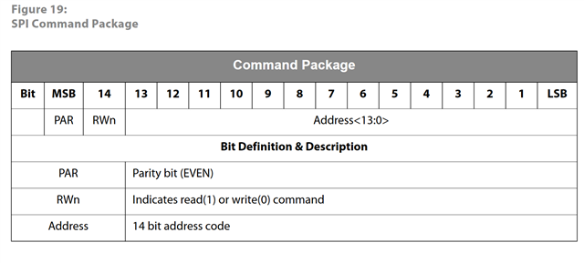
On AS5048A datasheet, the structure of the command package is [PAR RWn Address].
I've got the parity bit, R_w, and address_data. Could you please let me know how can I make the command structure using this?
Thank you so much for your help!
//###########################################################################
//
// FILE: Example_2806xSpi_FFDLB.c
//
// TITLE: SPI Digital Loop Back Example
//
//! \addtogroup f2806x_example_list
//! <h1>SPI Digital Loop Back(spi_loopback)</h1>
//!
//! This program uses the internal loop back test mode of the peripheral.
//! Other then boot mode pin configuration, no other hardware configuration
//! is required. Interrupts are not used.
//!
//! A stream of data is sent and then compared to the received stream.
//! The sent data looks like this: \n
//! 0000 0001 0002 0003 0004 0005 0006 0007 .... FFFE FFFF \n
//! This pattern is repeated forever.
//!
//! \b Watch \b Variables \n
//! - \b sdata , sent data
//! - \b rdata , received data
//
////###########################################################################
// $TI Release: $
// $Release Date: $
// $Copyright:
// Copyright (C) 2009-2022 Texas Instruments Incorporated - http://www.ti.com/
//
// Redistribution and use in source and binary forms, with or without
// modification, are permitted provided that the following conditions
// are met:
//
// Redistributions of source code must retain the above copyright
// notice, this list of conditions and the following disclaimer.
//
// Redistributions in binary form must reproduce the above copyright
// notice, this list of conditions and the following disclaimer in the
// documentation and/or other materials provided with the
// distribution.
//
// Neither the name of Texas Instruments Incorporated nor the names of
// its contributors may be used to endorse or promote products derived
// from this software without specific prior written permission.
//
// THIS SOFTWARE IS PROVIDED BY THE COPYRIGHT HOLDERS AND CONTRIBUTORS
// "AS IS" AND ANY EXPRESS OR IMPLIED WARRANTIES, INCLUDING, BUT NOT
// LIMITED TO, THE IMPLIED WARRANTIES OF MERCHANTABILITY AND FITNESS FOR
// A PARTICULAR PURPOSE ARE DISCLAIMED. IN NO EVENT SHALL THE COPYRIGHT
// OWNER OR CONTRIBUTORS BE LIABLE FOR ANY DIRECT, INDIRECT, INCIDENTAL,
// SPECIAL, EXEMPLARY, OR CONSEQUENTIAL DAMAGES (INCLUDING, BUT NOT
// LIMITED TO, PROCUREMENT OF SUBSTITUTE GOODS OR SERVICES; LOSS OF USE,
// DATA, OR PROFITS; OR BUSINESS INTERRUPTION) HOWEVER CAUSED AND ON ANY
// THEORY OF LIABILITY, WHETHER IN CONTRACT, STRICT LIABILITY, OR TORT
// (INCLUDING NEGLIGENCE OR OTHERWISE) ARISING IN ANY WAY OUT OF THE USE
// OF THIS SOFTWARE, EVEN IF ADVISED OF THE POSSIBILITY OF SUCH DAMAGE.
// $
//#############################################################################
//
// Included Files
//
#include "DSP28x_Project.h" // Device Headerfile and Examples Include File
//
// Function Prototypes
//
void spi_xmit(Uint16 a); // Gu : this seems like spiWrite in F2802x
void spi_fifo_init(void);
void spi_init(void);
void error(void);
//
// Main
//
void main(void)
{
Uint16 sdata; // send data
Uint16 rdata; // received data
//
// Step 1. Initialize System Control:
// PLL, WatchDog, enable Peripheral Clocks
// This example function is found in the F2806x_SysCtrl.c file.
//
InitSysCtrl();
//
// Step 2. Initalize GPIO:
// This example function is found in the F2806x_Gpio.c file and
// illustrates how to set the GPIO to it's default state.
//
//InitGpio(); // Skipped for this example
//
// Setup only the GP I/O only for SPI-A functionality
// This function is found in F2806x_Spi.c
//
InitSpiaGpio();
//
// Step 3. Clear all interrupts and initialize PIE vector table:
// Disable CPU interrupts
//
DINT;
//
// Initialize PIE control registers to their default state.
// The default state is all PIE interrupts disabled and flags
// are cleared.
// This function is found in the F2806x_PieCtrl.c file.
//
InitPieCtrl();
//
// Disable CPU interrupts and clear all CPU interrupt flags
//
IER = 0x0000;
IFR = 0x0000;
//
// Initialize the PIE vector table with pointers to the shell Interrupt
// Service Routines (ISR).
// This will populate the entire table, even if the interrupt
// is not used in this example. This is useful for debug purposes.
// The shell ISR routines are found in F2806x_DefaultIsr.c.
// This function is found in F2806x_PieVect.c.
//
InitPieVectTable();
//
// Step 4. Initialize all the Device Peripherals:
// This function is found in F2806x_InitPeripherals.c
//
//InitPeripherals(); // Not required for this example
spi_fifo_init(); // Initialize the Spi FIFO
spi_init(); // init SPI
//
// Step 5. User specific code:
// Interrupts are not used in this example.
//
sdata = 0x0000;
for(;;)
{
//
// Transmit data
//
spi_xmit(sdata);
//
// Wait until data is received
//
while(SpibRegs.SPIFFRX.bit.RXFFST !=1)
{
}
//
// Check against sent data
//
rdata = SpibRegs.SPIRXBUF;
if(rdata != sdata)
{
error();
}
sdata++;
}
}
//
// error - Step 7. Insert all local Interrupt Service Routines (ISRs)
// and functions here
//
void
error(void)
{
__asm(" ESTOP0"); // Test failed!! Stop!
for (;;);
}
//
// spi_init -
//
void
spi_init()
{
SpiaRegs.SPICCR.all =0x000F; // Reset on, rising edge, 16-bit char bits
//
// Enable master mode, normal phase, enable talk, and SPI int disabled.
//
SpiaRegs.SPICTL.all =0x0006;
SpiaRegs.SPIBRR =0x007F;
SpiaRegs.SPICCR.all =0x009F; // Relinquish SPI from Reset
SpiaRegs.SPIPRI.bit.FREE = 1; // Set so breakpoints don't disturb xmission
}
//
// spi_xmit -
//
void
spi_xmit(Uint16 a)
{
SpiaRegs.SPITXBUF=a;
}
//
// spi_fifo_init -
//
void
spi_fifo_init(void)
{
//
// Initialize SPI FIFO registers
//
SpiaRegs.SPIFFTX.all=0xE040;
SpiaRegs.SPIFFRX.all=0x2044;
SpiaRegs.SPIFFCT.all=0x0;
}
void AS5048A_motor1(void)
{
EALLOW;
GpioCtrlRegs.GPAQSEL2.bit.GPIO16 =3; // Asynch input GPIO16 (SPISIMOA)
GpioCtrlRegs.GPAQSEL2.bit.GPIO17 =3; // Asynch input GPIO17 (SPISOMIA)
GpioCtrlRegs.GPAQSEL2.bit.GPIO18 =3; // Asynch input GPIO18 (SPICLKA)
GpioCtrlRegs.GPAQSEL2.bit.GPIO19 =3; // Asynch input GPIO19 (Slave select)
GpioCtrlRegs.GPAMUX2.bit.GPIO16 = 1; // Configure GPIO16 as SPISIMOA
GpioCtrlRegs.GPAMUX2.bit.GPIO17 = 1; // Configure GPIO17 as SPISOMIA
GpioCtrlRegs.GPAMUX2.bit.GPIO18 = 1; // Configure GPIO18 as SPICLKA
GpioCtrlRegs.GPAQSEL2.bit.GPIO19 = 0; // Configure GPIO19 as GPIO for Slave select
GpioCtrlRegs.GPADIR.bit.GPIO19 = 1; //output
EDIS;
SpiaRegs.SPICCR.bit.SPISWRESET=0; //reset
SpiaRegs.SPICCR.bit.CLKPOLARITY=0;
SpiaRegs.SPICTL.bit.CLK_PHASE=0;
SpiaRegs.SPICCR.bit.SPILBK=0; //Loop back disable
SpiaRegs.SPICCR.bit.SPICHAR=0xF; //16 bit Character Length
SpiaRegs.SPICTL.bit.OVERRUNINTENA=0;
SpiaRegs.SPICTL.bit.SPIINTENA=0;
SpiaRegs.SPICTL.bit.MASTER_SLAVE=1; //master
SpiaRegs.SPICTL.bit.TALK=1; //4 wire
SpiaRegs.SPIBRR =10; //SPICLK=LSPCLK/(SPIBRR+1)-->SPICLK=(90/4)/(10+1)=2Mhz
SpiaRegs.SPIPRI.bit.FREE = 1;
SpiaRegs.SPIPRI.bit.SOFT = 0;
SpiaRegs.SPIPRI.bit.STEINV = 1;
SpiaRegs.SPIPRI.bit.TRIWIRE = 0;
SpiaRegs.SPICCR.bit.SPISWRESET=1;
}
void EN_AS5048A_SPI_motor1(void)
{
EALLOW;
GpioDataRegs.GPACLEAR.bit.GPIO19 = 1; // EN_AS5048A
EDIS;
}
void DIS_AS5048A_SPI_motor1(void)
{
EALLOW;
GpioDataRegs.GPASET.bit.GPIO19 = 1; // DIS_AS5048A
EDIS;
DELAY_US(1);
}
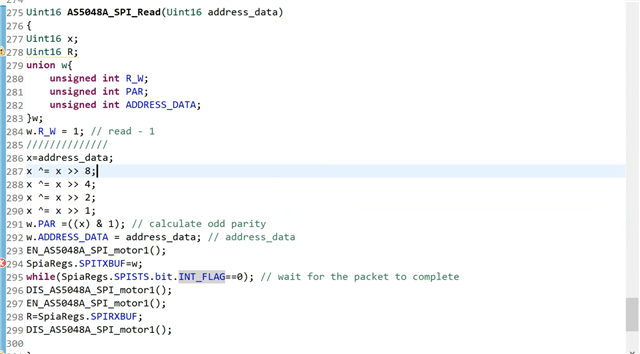
Uint16 AS5048A_SPI_Read(Uint16 address_data)
{
Uint16 x;
Uint16 R;
union w{
unsigned int R_W;
unsigned int PAR;
unsigned int ADDRESS_DATA;
}w;
w.R_W = 1; // read - 1
//////////////
x=address_data;
x ^= x >> 8;
x ^= x >> 4;
x ^= x >> 2;
x ^= x >> 1;
w.PAR =((x) & 1); // calculate odd parity
w.ADDRESS_DATA = address_data; // address_data
EN_AS5048A_SPI_motor1();
SpiaRegs.SPITXBUF=w;
while(SpiaRegs.SPISTS.bit.INT_FLAG==0); // wait for the packet to complete
DIS_AS5048A_SPI_motor1();
EN_AS5048A_SPI_motor1();
R=SpiaRegs.SPIRXBUF;
DIS_AS5048A_SPI_motor1();
}
//void AS5048A_SPI_WRITE_WORD_REG(Uint16_t data)
//{
//
//}
//
// End of File
//
