Other Parts Discussed in Thread: DRV8316, , DRV8316REVM, DAC128S085EVM
I'm evaluating InstaSPIN-FOC and the DRV8316 for sensorless FOC of a small custom motor with a magnetic suspension. I'm using a LAUNCHXL-F280025C and a DRV8316REVM trying to follow the Universal Motor Control Lab (SPRUJ26). I decided to try it with an off the shelf BLDC motor in case the custom motor test fixture I have was introducing problems. I'm using a 57BLR50-24-01 motor. It does have hall sensors built in but I'm not using them since my application needs to be sensorless. I measured phase-phase DC resistance at 8.6 ohms and phase-phase inductance at 419uH. Its nominal ratings are 24V, 3500RPM. I am using a 16V power supply.
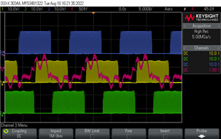
After some tweaking I can get the motor to spin in open loop on build 2 of the lab, but the current waveforms aren't even close to sinusoidal. Unfortunately the DAC128S085EVM boards are not available right now so I can't get the analog outputs described in the lab. Here's a scope capture with the first three channels on the three phases of the motor and the red channel is a clip-on current probe on one phase. After a rough and jagged start the motor runs very smoothly at 70Hz electrical (2100RPM) and draws 200mA of current. I have to start it at 40Hz and then increase it to 70 - it won't start directly at 70Hz.

I had to adjust the V/f profile numbers to get to this point. Here are the values used:
#define USER_MOTOR1_FREQ_LOW_HZ (12.0f) // Hz
#define USER_MOTOR1_FREQ_HIGH_HZ (116.0f) // Hz
#define USER_MOTOR1_VOLT_MIN_V (3.0f) // Volt
#define USER_MOTOR1_VOLT_MAX_V (16.0f) // Volt
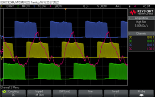
For example, if I change VOLT_MAX_V to 17.5, the motor can still run but draws 730mA and the current waveform looks like this:

Closer to sinusoidal, but drawing more current.
I have used the DATALOG tool to make graphs of current, voltage, and angle readings at the settings in the first scope capture.
Current:
Voltage:
Force Angle Generator:
Estimator:
I don't know why the estimator reading is so wrong. I have seen it be correct before with the custom motor, but this is what it looked like with the settings documented here.
Any ideas why my current waveform is so far from sinusoidal? The lab document shows a picture of a very clean sine wave but doesn't give any guidance on what to do if yours doesn't look that way. I think I have followed the lab instructions fully, but I must be missing something. I thought it might be related to core saturation from an incorrect V/f slope, but doesn't core saturation result in higher currents? Mine is showing this strange waveform at the lowest total current draw I have seen.

