


Other Parts Discussed in Thread: DRV8316REVM, C2000WARE, LAUNCHXL-F280049C, BOOSTXL-DRV8320RS, DRV8316, DRV8323, MOTORWARE, DRV8320
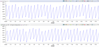
I'm working on a sensorless FOC drive for a very small custom PMSM pump motor with a magnetically levitated axial suspension. I have a LAUNCHXL-F280025C connected to a DRV8316REVM and I am trying to follow the universal motor control lab document (SPRUJ26). I have everything working through step 3 which uses closed loop control, but with a generic ramp generator as the angle signal rather than using the FAST or eSMO angle estimation schemes. The pump spins just fine using build 3. I set Iqd_set_A to 0.5 to reduce the drive current to 170mA or so and everything looks great. The estimator waveforms appears to be correct. Here's the DATALOG graph output with the force angle generator on top and estimator on bottom:
motorVars_M1.speed_Hz does track speedRef_Hz well and stays within a few Hz. Here's a scope capture of the drive waveforms where the first three channels are on the three motor phases and the red channel is a clip on current probe:
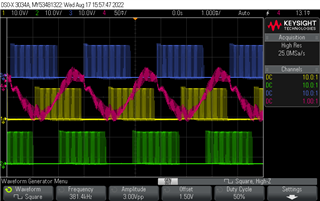
Here the motor is running at 350Hz electrical (10500 RPM). It's not quite sinusoidal - is that a problem? If so, what should I adjust?
My user_mtr1.h settings are:
#define USER_MOTOR1_Rr_Ohm (5.7) // DC resistance phase-phase measured
#define USER_MOTOR1_Rs_Ohm (5.7)
#define USER_MOTOR1_Ls_d_H (0.000223) // series L phase-phase measured
#define USER_MOTOR1_Ls_q_H (0.000223)
#define USER_MOTOR1_RATED_FLUX_VpHz (0.04) //
#define USER_MOTOR1_FREQ_LOW_HZ (100.0f) // Hz
#define USER_MOTOR1_FREQ_HIGH_HZ (800.0f) // Hz
#define USER_MOTOR1_VOLT_MIN_V (16.0f) // Volt
#define USER_MOTOR1_VOLT_MAX_V (24.0f) // Volt
The R and L values are measured and the flux value was figured out by trial and error until the estimator and speed readings looked right. I included the V/f ratio values even though I'm pretty sure they don't matter for closed loop drive.
Based on all of this it seems to me that I am ready to move on to build 4 where the angle estimator is engaged. However, when I run build 4 the drive goes all over the place. It constantly jitters between different drive levels and the waveforms on the scope go crazy. Draws about 1.5A. This actually makes sense to me because as far as I can tell it goes straight into relying on the estimated rotor angle without spinning up in open loop first. Is that right? Isn't the estimated angle useless until the motor is already spun up? My impression is that any FOC scheme has to go through an alignment and open loop spin up before switching to closed loop operation. Is there any provision for that in this code?
Edit:
In searching on the forum here I came across this post which references to the R/L ratio of the motor being a factor. For my motor the ratio is 5.7/0.000223 = 25560. I think that qualifies it as a "low inductance" motor and thus needs a higher PWM frequency (and control freq?). It appears to be set in user_mtr1.h:
//! \brief Defines the Pulse Width Modulation (PWM) frequency, kHz
//!
#define USER_M1_PWM_FREQ_kHz ((float32_t)(60.0f))
#define USER_M1_PWM_TBPRD_NUM (uint16_t)(USER_SYSTEM_FREQ_MHz * 1000.0f / USER_M1_PWM_FREQ_kHz / 2.0f)
and I figured out that you also have to change USER_M1_NUM_PWM_TICKS_PER_ISR_TICK so the ISR isn't trying to run too fast. I set it to 3 and PWM freq to 100kHz, which should mean a slight increase of the ISR control loop frequency from 30kHz to 33.3kHz, both of which are above my 25560 R/L. There doesn't seem to be any change. Step 3 still works fine and step 4 still goes crazy. I tried the automatic motor parameter identification on step 4 and it spat out the values R=15.29, L=9.99e-07, flux=2.95, R/L ~ 15000. Still went crazy when I hit run.
Edit 2:
Am I even using the right lab guide? Looking through the motorcontrol SDK files I see a similarly named but totally different lab guide located at C:\ti\c2000\C2000Ware_MotorControl_SDK_4_00_00_00\solutions\common\sensorless_foc\docs\labs\MotorControl SDK InstaSPIN Lab Guide.pdf. Looking inside it seems to only support the LAUNCHXL-F280049C which I do have and the BOOSTXL-DRV8320RS which I do not have. Is it possible to get that lab to work with the DRV8316 I am using? Which lab guide should I be trying to follow? It looks like other forum posts are referencing that lab guide rather than the "universal" one I am using. And what is the deal with the GUI? I'm a bit confused.
