This thread has been locked.

If you have a related question, please click the "Ask a related question" button in the top right corner. The newly created question will be automatically linked to this question.

TMS320F280049C: MCU reset actively with 20ms interval

Part Number: TMS320F280049C
Other Parts Discussed in Thread: LAUNCHXL-F280049C, UNIFLASH, C2000WARE

Hello,

Based on the project example "flashapi_ex1_program_autoecc", I add an reading a word from Sector6_start, and run the code on demo board Launchxl-F280049c, I found that, the MCU will reset with 20ms period. So, I need your help, tks!

see the details as bellow:

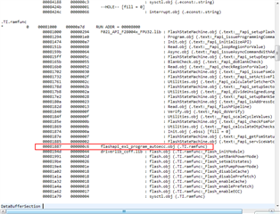
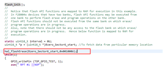
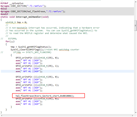
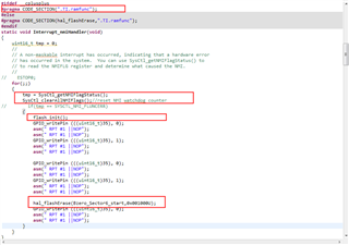
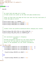
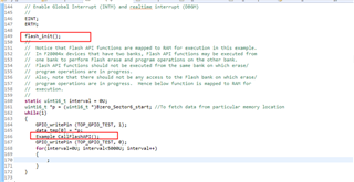
1.Based on example code, move the initialization part of Example_CallfFlashAPI () to flash_ init(), keeping the rest of the code(erase and program) in Example_CallfFlashAPI ().

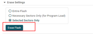
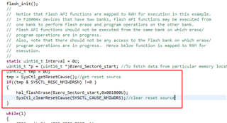
2.Flash_ Init() is placed after ERIM, and Example_CallfFlashAPI () is placed in while (1);

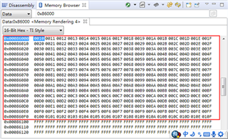
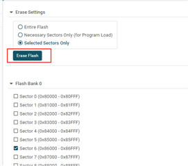
3.Read a word from  Sector6_start before calling Example_CallfFlashAPI (): uint16_t *p = (uint16_t *)Bzero_Sector6_start; data_tmp[0] = *p;

4. Use GPIO35 as debug output;

Please refer to the following code:

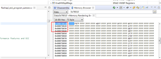
5.Download to demo board, pressXRSn repeatedly. After several times, MCU will reset actively at 20ms interval. It can only be recovered by flashing code with JTAG. The measured waveforms are as follows:

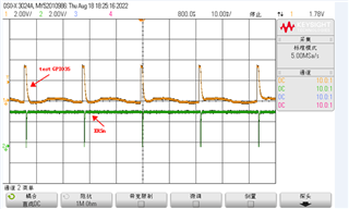
6.Use the GPIO35, I can confirm that, the MCU ran away when calling read flash:data_tmp[0] = *p;

Is there any improper operation?

Look forward to your reply, tks

  • Hi,

    Is watchdog enabled?  If yes, is it serviced periodically as needed?

    Thanks and regards,

    Vamsi

  • Hi Vamsi,

    The watchdog is disabled. The code can run normally unless pressing the XRSn frequently to simulate the power down and on. Once the abnormality occurs, the content in sector6 have been damaged:

    the sector6 data after abnormality:

    the sector6 data before abnormality:

     I have found that, there are two ways to recovery: download the code via CCS or only erase sector6 via uniflash.

    I guess that, by pressing XRSn frequently, the board may be powered down when erase or program flash is executing, and then will cause damage to the sector6. 

    I also tried to erase the sector6 by code in NMI handler, but it can not erase it successfully. please help analysis, thanks.

  • Hi Vamsi,

    I insert the whole code as below:

    //#############################################################################
    //
    // FILE:   flashapi_ex1_program_autoecc.c
    //
    // TITLE:  Flash programming example for AutoEcc option
    //
    //! \addtogroup driver_example_list
    //! <h1> Flash Programming for AutoECC </h1>
    //!
    //! This example demonstrates how to program Flash using API's AutoEcc 
    //! generation option.
    //!
    //! \b External \b Connections \n
    //!  - None.
    //!
    //! \b Watch \b Variables \n
    //!  - None.
    //!
    //
    //#############################################################################
    // $TI Release: F28004x Support Library v1.07.00.00 $
    // $Release Date: Sun Sep 29 07:29:19 CDT 2019 $
    // $Copyright:
    // Copyright (C) 2019 Texas Instruments Incorporated - http://www.ti.com/
    //
    // Redistribution and use in source and binary forms, with or without 
    // modification, are permitted provided that the following conditions 
    // are met:
    // 
    //   Redistributions of source code must retain the above copyright 
    //   notice, this list of conditions and the following disclaimer.
    // 
    //   Redistributions in binary form must reproduce the above copyright
    //   notice, this list of conditions and the following disclaimer in the 
    //   documentation and/or other materials provided with the   
    //   distribution.
    // 
    //   Neither the name of Texas Instruments Incorporated nor the names of
    //   its contributors may be used to endorse or promote products derived
    //   from this software without specific prior written permission.
    // 
    // THIS SOFTWARE IS PROVIDED BY THE COPYRIGHT HOLDERS AND CONTRIBUTORS 
    // "AS IS" AND ANY EXPRESS OR IMPLIED WARRANTIES, INCLUDING, BUT NOT 
    // LIMITED TO, THE IMPLIED WARRANTIES OF MERCHANTABILITY AND FITNESS FOR
    // A PARTICULAR PURPOSE ARE DISCLAIMED. IN NO EVENT SHALL THE COPYRIGHT 
    // OWNER OR CONTRIBUTORS BE LIABLE FOR ANY DIRECT, INDIRECT, INCIDENTAL, 
    // SPECIAL, EXEMPLARY, OR CONSEQUENTIAL DAMAGES (INCLUDING, BUT NOT 
    // LIMITED TO, PROCUREMENT OF SUBSTITUTE GOODS OR SERVICES; LOSS OF USE,
    // DATA, OR PROFITS; OR BUSINESS INTERRUPTION) HOWEVER CAUSED AND ON ANY
    // THEORY OF LIABILITY, WHETHER IN CONTRACT, STRICT LIABILITY, OR TORT 
    // (INCLUDING NEGLIGENCE OR OTHERWISE) ARISING IN ANY WAY OUT OF THE USE 
    // OF THIS SOFTWARE, EVEN IF ADVISED OF THE POSSIBILITY OF SUCH DAMAGE.
    // $
    //#############################################################################
    
    //
    // Included Files
    //
    #include "driverlib.h"
    #include "device.h"
    
    //
    // Include Flash API include file
    //
    #include "F021_F28004x_C28x.h"
    
    //
    // Include Flash API example header file
    //
    #include "flash_programming_f28004x.h"
    
    
    //
    // Defines
    //
    
    // Length (in 16-bit words) of data buffer used for program
    #define  WORDS_IN_FLASH_BUFFER    0xFF
    
    #define TOP_GPIO_TEST           ((uint16_t)35)/* test */
    //
    // Globals
    //
    
    //Data Buffers used for program operation using the flash API program function
    #pragma  DATA_SECTION(Buffer,"DataBufferSection");
    uint16   Buffer[WORDS_IN_FLASH_BUFFER + 1];
    uint32   *Buffer32 = (uint32 *)Buffer;
    
    
    //
    // Prototype of the functions used in this example
    //
    void Example_Error(Fapi_StatusType status);
    void Example_Done(void);
    void Example_CallFlashAPI(void);
    void FMSTAT_Fail(void);
    void flash_init(void);
    uint16_t data_tmp[8] = {0};
    
    //
    // Main
    //
    void main(void)
    {
    
    	//
        // Initialize device clock and peripherals
    	// Copy the Flash initialization code from Flash to RAM
        // Copy the Flash API from Flash to RAM
        // Configure Flash wait-states, fall back power mode, performance features and ECC
        //
        Device_init();
    
        //
        // Initialize GPIO
        //
        Device_initGPIO();
    
        //
        // Initialize PIE and clear PIE registers. Disables CPU interrupts.
        //
        Interrupt_initModule();
    
        //
        // Initialize the PIE vector table with pointers to the shell Interrupt
        // Service Routines (ISR).
        //
        Interrupt_initVectorTable();
    
        /* test */
        GPIO_setPadConfig (TOP_GPIO_TEST, GPIO_PIN_TYPE_STD);
        GPIO_setDirectionMode (TOP_GPIO_TEST, GPIO_DIR_MODE_OUT);
        GPIO_writePin (TOP_GPIO_TEST, 1);
        GPIO_setPinConfig (GPIO_35_GPIO35);
        asm(" RPT #1 ||NOP");
        asm(" RPT #1 ||NOP");
        asm(" RPT #1 ||NOP");
        asm(" RPT #1 ||NOP");
        GPIO_writePin (TOP_GPIO_TEST, 0);
    
        //
        // Enable Global Interrupt (INTM) and realtime interrupt (DBGM)
        //
        EINT;
        ERTM;
    
        flash_init();
        //
        //  Notice that Flash API functions are mapped to RAM for execution in this example.
        //  In F28004x devices that have two banks, Flash API functions may be executed from
        //  one bank to perform Flash erase and program operations on the other bank.
        //  Flash API functions should not be executed from the same bank on which erase/
        //  program operations are in progress.
        //  Also, note that there should not be any access to the Flash bank on which erase/
        //  program operations are in progress.  Hence below function is mapped to RAM for
        //  execution.
        //
        static uint16_t interval = 0U;
        uint16_t *p = (uint16_t *)Bzero_Sector6_start; //To fetch data from particular memory location
        while(1)
        {
            data_tmp[0] = *p;
            Example_CallFlashAPI();
            GPIO_writePin (TOP_GPIO_TEST, 0);
            for(interval=0U; interval<5000U; interval++)
            {
                ;
            }
        }
    
    }
    
    Fapi_StatusType oReturnCheck;
    Fapi_FlashStatusType oFlashStatus;
    Fapi_FlashStatusWordType oFlashStatusWord;
    
    void flash_init(void)
    {
        //
        // Note that wait-states are already configured in the Device_init().
        // However, if INTOSC is used as the clock source and
        // if the CPUCLK falls in the range (97,100] (check other ranges given in DS),
        // then an extra wait state is needed for FSM operations (erase/program).
        // Hence, below function call should be uncommented in case INTOSC is used.
        // At 100MHz, execution wait-states for external oscillator is 4 and hence
        // in this example, a wait-state of 5 is used below.
        // This example is using external oscillator as the clock source and hence
        // below is commented.
        //
        // This wait-state setting impacts both Flash banks. Applications which
        // perform simultaneous READ/FETCH of one bank and PROGRAM or ERASE of the other
        // bank must use the higher RWAIT setting during the PROGRAM or ERASE operation. OR
        // use a clock source or frequency with a common wait state setting
        // Example: Use 97MHz instead of 100MHz if it is acceptable for the application.
        //
        // In case, if user application increments wait-state before using API,
        // then remember to revert back to the original wait-state after the API usage
        // to avoid extra wait-state during application execution from Flash.
        //
        //
        // Flash_setWaitstates(FLASH0CTRL_BASE, 5);
    
        // Initialize the Flash API by providing the Flash register base address
        // and operating frequency.
        // This function is required to initialize the Flash API based on System frequency
        // before any other Flash API operation can be performed.
        // This function must also be called whenever System frequency or RWAIT is changed.
        oReturnCheck = Fapi_initializeAPI(F021_CPU0_BASE_ADDRESS, 100);
    
        if(oReturnCheck != Fapi_Status_Success)
        {
            // Check Flash API documentation for possible errors
            Example_Error(oReturnCheck);
        }
    
        // Initialize the Flash banks and FMC for erase and program operations.
        // Fapi_setActiveFlashBank() function sets the Flash banks and FMC for further
        // Flash operations to be performed on the banks.
        // Note: It does not matter which bank is passed as the parameter to initialize.
        //       Both Banks and FMC get initialized with one function call unlike F2837xS.
        //       Hence there is no need to execute Fapi_setActiveFlashBank() for each bank.
        //       Executing for one bank is enough.
        oReturnCheck = Fapi_setActiveFlashBank(Fapi_FlashBank0);
    
        if(oReturnCheck != Fapi_Status_Success)
        {
            // Check Flash API documentation for possible errors
            Example_Error(oReturnCheck);
        }
    
    }
    
    //*****************************************************************************
    //  Example_CallFlashAPI
    //
    //  This function will interface to the flash API.
    //  Flash API functions used in this function are executed from RAM in this
    //  example.
    //*****************************************************************************
    
    #ifdef __cplusplus
    #pragma CODE_SECTION(".TI.ramfunc");
    #else
    #pragma CODE_SECTION(Example_CallFlashAPI, ".TI.ramfunc");
    #endif
    void Example_CallFlashAPI(void)
    {
        uint32 u32Index = 0;
        uint16 i = 0;
        asm(" RPT #1 ||NOP");
        asm(" RPT #1 ||NOP");
        asm(" RPT #1 ||NOP");
        asm(" RPT #1 ||NOP");
        GPIO_writePin (TOP_GPIO_TEST, 0);
        asm(" RPT #1 ||NOP");
        asm(" RPT #1 ||NOP");
        asm(" RPT #1 ||NOP");
        asm(" RPT #1 ||NOP");
        GPIO_writePin (TOP_GPIO_TEST, 1);
        asm(" RPT #1 ||NOP");
        asm(" RPT #1 ||NOP");
        asm(" RPT #1 ||NOP");
        asm(" RPT #1 ||NOP");
    
        // Erase Flash Bank0 sector6
        oReturnCheck = Fapi_issueAsyncCommandWithAddress(Fapi_EraseSector,
                                            (uint32 *)Bzero_Sector6_start);
    
        // Wait until FSM is done with erase sector operation
        while (Fapi_checkFsmForReady() != Fapi_Status_FsmReady){}
    
    	if(oReturnCheck != Fapi_Status_Success)
    	{
    		// Check Flash API documentation for possible errors
    		Example_Error(oReturnCheck);
    	}
    
        // Read FMSTAT register contents to know the status of FSM after
        // erase command to see if there are any erase operation related errors
        oFlashStatus = Fapi_getFsmStatus();
        if(oFlashStatus != 0)
        {
            // Check Flash API documentation for FMSTAT and debug accordingly
            // Fapi_getFsmStatus() function gives the FMSTAT register contents.
        	// Check to see if any of the EV bit, ESUSP bit, CSTAT bit or
        	// VOLTSTAT bit is set (Refer to API documentation for more details).
        	FMSTAT_Fail();
        }
    
        // Do blank check
        // Verify that Bank0 sector6 is erased.  The Erase command itself does a verify as
        // it goes.  Hence erase verify by CPU reads (Fapi_doBlankCheck()) is optional.
        oReturnCheck = Fapi_doBlankCheck((uint32 *)Bzero_Sector6_start,
        		       Sector8KB_u32length,
                       &oFlashStatusWord);
    
        if(oReturnCheck != Fapi_Status_Success)
        {
            // Check Flash API documentation for error info
            Example_Error(oReturnCheck);
        }
    
    
        // A data buffer of max 8 16-bit words can be supplied to the program function.
        // Each word is programmed until the whole buffer is programmed or a
        // problem is found. However to program a buffer that has more than 8
        // words, program function can be called in a loop to program 8 words for
        // each loop iteration until the whole buffer is programmed.
        //
        // Remember that the main array flash programming must be aligned to
        // 64-bit address boundaries and each 64 bit word may only be programmed
        // once per write/erase cycle.  Meaning the length of the data buffer
        // (3rd parameter for Fapi_issueProgrammingCommand() function) passed
        // to the program function can only be either 4 or 8.
        //
        // Program data in Flash using "AutoEccGeneration" option.
        // When AutoEccGeneration opton is used, Flash API calculates ECC for the given
        // 64-bit data and programs it along with the 64-bit main array data.
        // Note that any unprovided data with in a 64-bit data slice
        // will be assumed as 1s for calculating ECC and will be programmed.
        //
        // Note that data buffer (Buffer) is aligned on 64-bit boundary for verify reasons.
        //
        // Monitor ECC address for Bank0 Sector6 while programming with AutoEcc mode.
        //
        // In this example, 0xFF+1 bytes are programmed in Flash Bank0 Sector6
        // along with auto-generated ECC.
    
        //
        // Fill a buffer with data to program into the flash.
        //
        for(i=0; i <= WORDS_IN_FLASH_BUFFER; i++)
        {
            Buffer[i] = 0x10+i;
        }
    
        for(i=0, u32Index = Bzero_Sector6_start;
           (u32Index < (Bzero_Sector6_start + WORDS_IN_FLASH_BUFFER)) &&
           (oReturnCheck == Fapi_Status_Success); i+= 8, u32Index+= 8)
        {
    		oReturnCheck = Fapi_issueProgrammingCommand((uint32 *)u32Index, Buffer+i, 8,
    																				 0, 0, Fapi_AutoEccGeneration);
    
    		// Wait until the Flash program operation is over
    		while(Fapi_checkFsmForReady() == Fapi_Status_FsmBusy);
    
    		if(oReturnCheck != Fapi_Status_Success)
    		{
    			// Check Flash API documentation for possible errors
    			Example_Error(oReturnCheck);
    		}
    
    		// Read FMSTAT register contents to know the status of FSM after
    		// program command to see if there are any program operation related errors
    		oFlashStatus = Fapi_getFsmStatus();
    		if(oFlashStatus != 0)
    		{
    			//Check FMSTAT and debug accordingly
    			FMSTAT_Fail();
    		}
    
    		// Verify the programmed values.  Check for any ECC errors.
    		// The program command itself does a verify as it goes.
    		// Hence program verify by CPU reads (Fapi_doVerify()) is optional.
            oReturnCheck = Fapi_doVerify((uint32 *)u32Index,
                                         4, Buffer32+(i/2),
                                         &oFlashStatusWord);
    
    		if(oReturnCheck != Fapi_Status_Success)
    		{
    			// Check Flash API documentation for possible errors
    			Example_Error(oReturnCheck);
    		}
        }
    
    /*
    	// Erase the sector that is programmed above
        // Erase Bank0 Sector6
        oReturnCheck = Fapi_issueAsyncCommandWithAddress(Fapi_EraseSector,
                       (uint32 *)Bzero_Sector6_start);
    
        // Wait until FSM is done with erase sector operation
        while (Fapi_checkFsmForReady() != Fapi_Status_FsmReady){}
    
    	if(oReturnCheck != Fapi_Status_Success)
    	{
    		// Check Flash API documentation for possible errors
    		Example_Error(oReturnCheck);
    	}
    
        // Read FMSTAT register contents to know the status of FSM after
        // erase command to see if there are any erase operation related errors
        oFlashStatus = Fapi_getFsmStatus();
        if(oFlashStatus != 0)
        {
            // Check Flash API documentation for FMSTAT and debug accordingly
            // Fapi_getFsmStatus() function gives the FMSTAT register contents.
        	// Check to see if any of the EV bit, ESUSP bit, CSTAT bit or
        	// VOLTSTAT bit is set (Refer to API documentation for more details).
        	FMSTAT_Fail();
        }
    
        // Do blank check
        // Verify that Bank0 sector6 is erased.  The Erase command itself does a verify as
        // it goes.  Hence erase verify by CPU reads (Fapi_doBlankCheck()) is optional.
        oReturnCheck = Fapi_doBlankCheck((uint32 *)Bzero_Sector6_start,
        		       Sector8KB_u32length,
                       &oFlashStatusWord);
    
        if(oReturnCheck != Fapi_Status_Success)
        {
            // Check Flash API documentation for error info
            Example_Error(oReturnCheck);
        }
    
        // In case, if user application increments wait-state before using API
        // for INTOSC reason, then remember to revert back (uncomment below funcion call)
        // to the original wait-state after the API usage to avoid extra wait-state
        // during application execution from Flash.
        // At 100MHz, execution wait-states is 4 and hence in this example,
        // a wait-state of 4 is used below.
        //
        // Flash_setWaitstates(FLASH0CTRL_BASE, 4);
    
        // Example is done here*/
    
    
    //    Example_Done();
    }
    
    //******************************************************************************
    // For this example, just stop here if an API error is found
    //******************************************************************************
    void Example_Error(Fapi_StatusType status)
    {
        //  Error code will be in the status parameter
            __asm("    ESTOP0");
    }
    
    //******************************************************************************
    //  For this example, once we are done just stop here
    //******************************************************************************
    void Example_Done(void)
    {
        __asm("    ESTOP0");
    }
    
    //******************************************************************************
    // For this example, just stop here if FMSTAT fail occurs
    //******************************************************************************
    void FMSTAT_Fail(void)
    {
        //  Error code will be in the status parameter
            __asm("    ESTOP0");
    }
    
    
    //
    // End of File
    //
    

  • Hi,

    Why are you doing frequent resets during erase or program operations?  Reset during erase or program operation can corrupt the flash contents.

    Regarding recovery: If Uniflash is able to recover, CCS also can recover it.  You can select erasing sector 6 in CCS flash plugin GUI.  

    Do you want me to review your code to know why your code is not able to erase the device after the frequent resets?

    Thanks and regards,

    Vamsi

  • Hi Vamsi,

    In our products, we need use one sector to store several data, therefore, we should read all content from this sector before erase-program sequence, and then program these new data into this sector again. But it is abnormal at customer side, and we found the above issue. Then we tried to test the same FLASH function on demo example, it aslo occurred.

    My question is, whether these are wrong with my code?  If power down during erase or program operation can corrupt the flash contents, are there any recovery methods without erased by external tool? In practical application, we can't determine the power down time, so the abnormality is inevitable, and we should take a recovery mechanism, how should we do?

    thanks.

  • Hi,

    I will review and get back to you in a day or two.

    Thanks and regards,
    Vamsi

  • Hi,

    After a reset, does your application (assuming flash boot) configure the PLL etc correctly, and configure the flash wait-states etc. before calling the flash API functions to do the erase?

    Where is the flash API executed from?  Hope it is executed from RAM (or ROM).

    Thanks and regards,
    Vamsi

  • Hi Vamsi,

    Thanks for you support!

    Based on TI flashapi_ex1_program_autoecc, I just add read a words data from Bzero_Sector6_start and add one debug GPIO for testing. After a reset, the MCU will execute the same source code.

    I referred to the source code, in Device_init() function, PLL  and Flash maintain the original configuration. The cmd file also hasn't beeb changed.

    void Device_init(void)
    {
        //
        // Disable the watchdog
        //
        SysCtl_disableWatchdog();
    
    #ifdef _FLASH
        //
        // Copy time critical code and flash setup code to RAM. This includes the
        // following functions: InitFlash();
        //
        // The RamfuncsLoadStart, RamfuncsLoadSize, and RamfuncsRunStart symbols
        // are created by the linker. Refer to the device .cmd file.
        //
        memcpy(&RamfuncsRunStart, &RamfuncsLoadStart, (size_t)&RamfuncsLoadSize);
    #endif
    
        //
        // Set up PLL control and clock dividers
        //
        SysCtl_setClock(DEVICE_SETCLOCK_CFG);
    
        //
        // Make sure the LSPCLK divider is set to the default (divide by 4)
        //
        SysCtl_setLowSpeedClock(SYSCTL_LSPCLK_PRESCALE_4);
    
        //
        // These asserts will check that the #defines for the clock rates in
        // device.h match the actual rates that have been configured. If they do
        // not match, check that the calculations of DEVICE_SYSCLK_FREQ and
        // DEVICE_LSPCLK_FREQ are accurate. Some examples will not perform as
        // expected if these are not correct.
        //
        ASSERT(SysCtl_getClock(DEVICE_OSCSRC_FREQ) == DEVICE_SYSCLK_FREQ);
        ASSERT(SysCtl_getLowSpeedClock(DEVICE_OSCSRC_FREQ) == DEVICE_LSPCLK_FREQ);
    
        //
        // Call Flash Initialization to setup flash waitstates. This function must
        // reside in RAM.
        //
        Flash_initModule(FLASH0CTRL_BASE, FLASH0ECC_BASE, DEVICE_FLASH_WAITSTATES);
    
        //
        // Turn on all peripherals
        //
        Device_enableAllPeripherals();
    }

  • Hi,

    Are you using RAM config or flash config linker command file?

    Are you executing ROM flash API?  Or is the flash API mapped to a sector and copied to RAM?  If mapped to a sector, which bank/sector is it?

    Thanks and regards,
    Vamsi

  • Hi Vamsi,

    I use flash config linker cmd as below, Flash API is mapped into FLASH_BANK0_SEC1, and copied to RAM for running.

    MEMORY
    {
    PAGE 0 :
       /* BEGIN is used for the "boot to Flash" bootloader mode   */
    
       BEGIN           	: origin = 0x080000, length = 0x000002
       RAMM0           	: origin = 0x0000F5, length = 0x00030B
    
       RAMLS03        	: origin = 0x008000, length = 0x002000
       RAMLS4      		: origin = 0x00A000, length = 0x000800
       RESET           	: origin = 0x3FFFC0, length = 0x000002
    
       /* Flash sectors */
       /* BANK 0 */
       FLASH_BANK0_SEC0  : origin = 0x080002, length = 0x000FFE	/* on-chip Flash */
       FLASH_BANK0_SEC1  : origin = 0x081000, length = 0x001000	/* on-chip Flash */
       FLASH_BANK0_SEC2  : origin = 0x082000, length = 0x001000	/* on-chip Flash */
       FLASH_BANK0_SEC3  : origin = 0x083000, length = 0x001000	/* on-chip Flash */
       FLASH_BANK0_SEC4  : origin = 0x084000, length = 0x001000	/* on-chip Flash */
       FLASH_BANK0_SEC5  : origin = 0x085000, length = 0x001000	/* on-chip Flash */
       FLASH_BANK0_SEC6  : origin = 0x086000, length = 0x001000	/* on-chip Flash */
       FLASH_BANK0_SEC7  : origin = 0x087000, length = 0x001000	/* on-chip Flash */
       FLASH_BANK0_SEC8  : origin = 0x088000, length = 0x001000	/* on-chip Flash */
       FLASH_BANK0_SEC9  : origin = 0x089000, length = 0x001000	/* on-chip Flash */
       FLASH_BANK0_SEC10 : origin = 0x08A000, length = 0x001000	/* on-chip Flash */
       FLASH_BANK0_SEC11 : origin = 0x08B000, length = 0x001000	/* on-chip Flash */
       FLASH_BANK0_SEC12 : origin = 0x08C000, length = 0x001000	/* on-chip Flash */
       FLASH_BANK0_SEC13 : origin = 0x08D000, length = 0x001000	/* on-chip Flash */
       FLASH_BANK0_SEC14 : origin = 0x08E000, length = 0x001000	/* on-chip Flash */
       FLASH_BANK0_SEC15 : origin = 0x08F000, length = 0x001000	/* on-chip Flash */
    
       /* BANK 1 */
       FLASH_BANK1_SEC0  : origin = 0x090000, length = 0x001000	/* on-chip Flash */
       FLASH_BANK1_SEC1  : origin = 0x091000, length = 0x001000	/* on-chip Flash */
       FLASH_BANK1_SEC2  : origin = 0x092000, length = 0x001000	/* on-chip Flash */
       FLASH_BANK1_SEC3  : origin = 0x093000, length = 0x001000	/* on-chip Flash */
       FLASH_BANK1_SEC4  : origin = 0x094000, length = 0x001000	/* on-chip Flash */
       FLASH_BANK1_SEC5  : origin = 0x095000, length = 0x001000	/* on-chip Flash */
       FLASH_BANK1_SEC6  : origin = 0x096000, length = 0x001000	/* on-chip Flash */
       FLASH_BANK1_SEC7  : origin = 0x097000, length = 0x001000	/* on-chip Flash */
       FLASH_BANK1_SEC8  : origin = 0x098000, length = 0x001000	/* on-chip Flash */
       FLASH_BANK1_SEC9  : origin = 0x099000, length = 0x001000	/* on-chip Flash */
       FLASH_BANK1_SEC10 : origin = 0x09A000, length = 0x001000	/* on-chip Flash */
       FLASH_BANK1_SEC11 : origin = 0x09B000, length = 0x001000	/* on-chip Flash */
       FLASH_BANK1_SEC12 : origin = 0x09C000, length = 0x001000	/* on-chip Flash */
       FLASH_BANK1_SEC13 : origin = 0x09D000, length = 0x001000	/* on-chip Flash */
       FLASH_BANK1_SEC14 : origin = 0x09E000, length = 0x001000	/* on-chip Flash */
       FLASH_BANK1_SEC15 : origin = 0x09F000, length = 0x001000	/* on-chip Flash */
    
    PAGE 1 :
    
       BOOT_RSVD       : origin = 0x000002, length = 0x0000F3     /* Part of M0, BOOT rom will use this for stack */
       RAMM1           : origin = 0x000400, length = 0x000400     /* on-chip RAM block M1 */
    
       RAMLS5      : origin = 0x00A800, length = 0x000800
       RAMLS6      : origin = 0x00B000, length = 0x000800
       RAMLS7      : origin = 0x00B800, length = 0x000800
    
       RAMGS0      : origin = 0x00C000, length = 0x002000
       RAMGS1      : origin = 0x00E000, length = 0x002000
       RAMGS2      : origin = 0x010000, length = 0x002000
       RAMGS3      : origin = 0x012000, length = 0x002000
    }
    
    
    SECTIONS
    {
       codestart        : > BEGIN,     PAGE = 0, ALIGN(4)
       .text            : >>FLASH_BANK0_SEC1 | FLASH_BANK0_SEC2 | FLASH_BANK0_SEC3,   PAGE = 0, ALIGN(4)
       .cinit           : > FLASH_BANK0_SEC1,     PAGE = 0, ALIGN(4)
       .pinit           : > FLASH_BANK0_SEC1,     PAGE = 0, ALIGN(4)
       .switch          : > FLASH_BANK0_SEC1,     PAGE = 0, ALIGN(4)
       .reset           : > RESET,     PAGE = 0, TYPE = DSECT /* not used, */
    
       .cio             : > RAMLS03,    PAGE = 0
       .stack           : > RAMM1,     PAGE = 1
       .ebss            : > RAMLS5,    PAGE = 1
       .esysmem         : > RAMLS5,    PAGE = 1   
       .econst          : > FLASH_BANK0_SEC4,    PAGE = 0, ALIGN(4)
    
       ramgs0           : > RAMGS0,    PAGE = 1
       ramgs1           : > RAMGS1,    PAGE = 1
    
       GROUP
       {
           .TI.ramfunc
           { -l F021_API_F28004x_FPU32.lib}
    
       } LOAD = FLASH_BANK0_SEC1,
         RUN = RAMLS03,
         LOAD_START(_RamfuncsLoadStart),
         LOAD_SIZE(_RamfuncsLoadSize),
         LOAD_END(_RamfuncsLoadEnd),
         RUN_START(_RamfuncsRunStart),
         RUN_SIZE(_RamfuncsRunSize),
         RUN_END(_RamfuncsRunEnd),
         PAGE = 0, ALIGN(4)
    
       DataBufferSection : > RAMM1, PAGE = 1, ALIGN(4)
    }
    
    /*
    //===========================================================================
    // End of file.
    //===========================================================================
    */
    

  • Hi,

    I reviewed the code at a high-level and I didn't see any issue.  

    What is the exact error (and FMSTAT) that you get for erase when using API?  

    Thanks and regards,

    Vamsi

  • Hi Vamsi,

    I observed that the XRSn pin will actively output low level with 20ms interval, you can refer to the following waveform captured in abnorma case, thanks.

  • Hi,

    Maybe a NMI reset due to flash ECC error.  

    Does your application read the sector 6 that has invalid data/ECC?

    Thanks and regards,
    Vamsi

  • Hi Vamsi,

    Yes, as you said, I inserted some debug code into source code and found that, after the abnormality occurred, the MCU entered into Interrupt_nmiHandler(void) when executing read one word from Bzero_Sector6_start. The SYSCTL_NMI_FLUNCERR flag can be read as 1 in NMI interrupt. I tried to erase the Sector6 in NMI interrupt, but the error can not disappear. Please refer to the following NMI code which I wrote in the file interrupt.c:

    static void Interrupt_nmiHandler(void)
    {
        uint16_t tmp = 0;
        //
        // A non-maskable interrupt has occurred, indicating that a hardware error
        // has occurred in the system.  You can use SysCtl_getNMIFlagStatus() to
        // to read the NMIFLG register and determine what caused the NMI.
        //
    //    ESTOP0;
    
        for(;;)
        {
    
            tmp = SysCtl_getNMIFlagStatus();
            SysCtl_clearAllNMIFlags();//reset NMI watchdog counter
            if(tmp == SYSCTL_NMI_FLUNCERR)
            {
                GPIO_writePin (TOP_GPIO_TEST, 0);
                asm(" RPT #1 ||NOP");
                asm(" RPT #1 ||NOP");
                GPIO_writePin (TOP_GPIO_TEST, 1);
                asm(" RPT #1 ||NOP");
                asm(" RPT #1 ||NOP");
    
                GPIO_writePin (TOP_GPIO_TEST, 0);
                asm(" RPT #1 ||NOP");
                asm(" RPT #1 ||NOP");
    
                GPIO_writePin (TOP_GPIO_TEST, 1);
                asm(" RPT #1 ||NOP");
                asm(" RPT #1 ||NOP");
                hal_flashErase(0x09E000,0x001000U);//try to erase corrupt sector
                GPIO_writePin (TOP_GPIO_TEST, 0);
                asm(" RPT #1 ||NOP");
                asm(" RPT #1 ||NOP");
            }
    
    
        }
    }

    I also found that, if use the uniflash to erase sector6 only, the error can disappear and MCU ran as expected. I didn't know erase operation difference between uniflash and call erase API.

    Is there any method to resolve this error by code?

    Thank you for the support!

  • Hi,

    I will review and get back to you in couple of days.

    Thanks and regards,

    Vamsi

  • Hi,

    Maybe the NMI watchdog is causing a reset and halting the erase.

    I will ask our System control expert to take a look at your NMI handler.

    Also, can you share the code of hal_flashErase()?

    Thanks and regards,
    Vamsi

  • Hi Vamsi,

    Thank you very much.

    Please refer to the following function,which is called in NMI handler code

    //
    // Erase Flash Sector
    //
    #pragma CODE_SECTION(hal_flashErase,".TI.ramfunc");
    uint16 hal_flashErase (uint32 StartSector, uint32 u32Length)
    {
    
        oReturnCheck = Fapi_issueAsyncCommandWithAddress (Fapi_EraseSector,
                                                          (uint32 *) StartSector);
    
        // Wait until FSM is done with erase sector operation
        while (Fapi_checkFsmForReady () != Fapi_Status_FsmReady) {
        }
    
    
        if (oReturnCheck != Fapi_Status_Success) {
            // Check Flash API documentation for possible errors
            return oReturnCheck;
        }
    
        // Read FMSTAT register contents to know the status of FSM after
        // erase command to see if there are any erase operation related errors
        oFlashStatus = Fapi_getFsmStatus ();
        if (oFlashStatus != 0) {
            // Check Flash API documentation for FMSTAT and debug accordingly
            // Fapi_getFsmStatus() function gives the FMSTAT register contents.
            // Check to see if any of the EV bit, ESUSP bit, CSTAT bit or
            // VOLTSTAT bit is set (Refer to API documentation for more details).
            return oFlashStatus;
        }


        // Do blank check
        // Verify that Bank sector is erased.  The Erase command itself does a verify as
        // it goes.  Hence erase verify by CPU reads (Fapi_doBlankCheck()) is optional.
        oReturnCheck = Fapi_doBlankCheck ((uint32 *) StartSector, u32Length,
                                          &oFlashStatusWord);
    
        if (oReturnCheck != Fapi_Status_Success) {
            // Check Flash API documentation for error info
            return oReturnCheck;
        }
    
        return oReturnCheck;
    }

    Correct previous code in Interrupt_nmiHandler(): hal_flashErase(Bzero_Sector6_start,0x001000U)

    static void Interrupt_nmiHandler(void)
    {
        uint16_t tmp = 0;
        //
        // A non-maskable interrupt has occurred, indicating that a hardware error
        // has occurred in the system.  You can use SysCtl_getNMIFlagStatus() to
        // to read the NMIFLG register and determine what caused the NMI.
        //
    //    ESTOP0;
    
        for(;;)
        {
    
            tmp = SysCtl_getNMIFlagStatus();
            SysCtl_clearAllNMIFlags();//reset NMI watchdog counter
            if(tmp == SYSCTL_NMI_FLUNCERR)
            {
                GPIO_writePin (TOP_GPIO_TEST, 0);
                asm(" RPT #1 ||NOP");
                asm(" RPT #1 ||NOP");
                GPIO_writePin (TOP_GPIO_TEST, 1);
                asm(" RPT #1 ||NOP");
                asm(" RPT #1 ||NOP");
    
                GPIO_writePin (TOP_GPIO_TEST, 0);
                asm(" RPT #1 ||NOP");
                asm(" RPT #1 ||NOP");
    
                GPIO_writePin (TOP_GPIO_TEST, 1);
                asm(" RPT #1 ||NOP");
                asm(" RPT #1 ||NOP");
                hal_flashErase(Bzero_Sector6_start,0x001000U);//erase corrupt sector6
                GPIO_writePin (TOP_GPIO_TEST, 0);
                asm(" RPT #1 ||NOP");
                asm(" RPT #1 ||NOP");
            }
    
    
        }
    }

  • Hi,

    Are the functions flash_init() and hal_flashErase (uint32 StartSector, uint32 u32Length) mapped to execute from RAM?  If not, please map for RAM execution.

    Thanks and regards,

    Vamsi

  • Hi Vamsi,

    I have added #pragma CODE_SECTION(".TI.ramfunc") before flash_init() and hal_flashErase(), and the map file is below, thanks.

  • Hi,

    Could you send me your map file?  If you don't want to share it here, you can share on private chat.  Please remove the proprietary info (if any) from it.

    Thanks and regards,
    Vamsi

  • Hi Vamsi,

    I upload the project for your reference. 

    flashapi_ex1_program_autoecc.rar

  • Hi,

    Thank you, I will review it and get back to you early next week.

    Thanks and regards,

    Vamsi

  • Hi,

    On the erase failing device, if not in the NMI ISR, can you try to load the C2000Ware flash programming example as-is and see if that can erase the sector successfully?

    You can edit for the erase of the required sector.

    Thanks and regards,
    Vamsi

  • Hi Vamsi,

    On the erase failing device, once re-loaded the code by CCS or uniFlash, the whole sector can be erased successfully and running normally. We also try to only erase the sector6 by uniFlash, and after powered on, the device can also run normally. it indicates that, the corrupt sector6 can be erased by uniFlash, but can not be erased by source code?

  • Hi,

    Maybe my suggestion was not clear.  Please let me clarify:  Once the failure happens, instead of using CCS or Uniflash to erase, do a debugger reset and load the flash programming example and erase the sector 6 using that example.  Let me know how that goes.

    Thanks and regards,
    Vamsi

  • Hi Vamsi,

    Sorry, I didn't understand, how to load the RAM without connected CCS or uniFlash? Could you give operation guideline? thanks.

    Could you explain the difference between two erase operation: execute erase in uniflash and execute erase by calling F021 API.

  • Hi,

    There is no any difference in the erase process between the flash API and the CCS/Uniflash tool.

    Reason I asked you to run the C2000Ware flash API programming example is:  If that succeeds, that tells me that something in your application is not configured correctly for the flash erase.  

    Regarding the flash programming example:  When the flash sector 6 erase does not succeed with your application, please import the C:\ti\c2000\C2000Ware_x_xx_xx_xx\driverlib\f28004x\examples\flash\flashapi_ex1_program_autoecc.c project, compile it and then and load the executable to the device flash.  Before loading, please modify the flash plugin GUI's erase settings as shown below so that sector 6 does not get erased by the CCS flash plugin.  After loading, execute the example and see whether erase of sector 6 succeeds or not.  If it does not succeed, we can have a debug call/meeting to analyze further.  

    If you don't know how to navigate to the flash plugin GUI in CCS debug view, please see below:

    Please note:  Previously I suggested RAM load to ensure that flash won't get erased during load.  However, I felt it might take more time for you to create a RAM based example and hence suggested to configure the Erase Settings as shown above. 

    Thanks and regards,
    Vamsi

  • Thank you Vamsi,

    I will follow these step you mentioned, and give feedback. 

  • Hi,

    I will keep this thread in pause until you come back.

    Thanks and regards,
    Vamsi

  • Hi Vamsi,

    I have taken tests and have some founds:

    1. When the sector 6 has been corruptted, I download old code as you mentioned(uniFlash-->Necessary Sectors Only for Program Load ), and found the abnormality still exist.

    2.Next, I download the new code with the same operation, in new code, erase  function will be called to erase sector 6 as below, and found the abnormality is lost, it means the sector 6 has been erased successfully.

    3.I tried to move the erase function to NMI handler as below, but the abnormality still exists, it means the sector 6 can not be erased in NMI handler. 

    Now, I found a valid method to resolve this issue: In NMI handler, just execute empty loop: "for (;;)" , then it will trigger the NMI watchdog reset, and then NMIWDRSN reset source can be obtained. The code is as below, and MCU can be recovered from the abnormality.

    But, my question is, why the sector 6 can not be erased successfully in NMI handler? Do you know the reason? 

    Thank you for your great supports!

  • Hi,

    I will review and get back to you early next week.

    Thanks and regards,
    Vamsi

  • Hi,

    Thank you for trying the suggestion:  Since loading/executing the flash API example as-is without erasing Sector 6 while loading the example worked, I think it is not an issue with the flash API.  In your NMI handler, can you include the initialization routines as well like Fapi_initializeAPI() and Fapi_setActiveFlashbank() and see if that helps?  I feel this is an initialization issue. 

    Or it might be that the watchdog/NMIreset is kicking in before the erase is complete.

    Thanks and regards,

    Vamsi

  • Hi Vamsi,

    I also have tested your suggestion: the watchdog is always disabled, in NMI handler, before executing the erase sector6, the NMI flags are cleared to avoid NMI watchdog reset and the flash init() is called. But, the abnormality still exists. Please refer to the following NMI code

    Thanks,

  • Hi,

    Yes, I saw the NMI flag clearance previously in your code (asked our System control expert to ensure that it is properly handled by your code - I will follow-up with our system-control expert).  

    1) I understand that flash erase did not happen when you tried it in the NMI handler.  Question:  Did that erase code get completely executed?  Or is there any reset before that?  

    2) Could you share the flash_init()?

    Thanks and regards,
    Vamsi

  • Hi Vamsi,

    1). When I masked "SysCtl_clearAllNMIFlags();//reset NMI watchdog counter", once the abnormality occurred, the XRSn pin can be Low with 20ms interval. When I enable "SysCtl_clearAllNMIFlags();//reset NMI watchdog counter", once the abnormality occurred, the XRSn pin will be kept HIGH. This indicates that, once entered into NMI handler, the NMI watchdog will not reset MCU. 

    2). Please refer to the following flash_init() code which is called by main.c and NMI handler.

    Fapi_StatusType oReturnCheck;
    Fapi_FlashStatusType oFlashStatus;
    Fapi_FlashStatusWordType oFlashStatusWord;
    
    #ifdef __cplusplus
    #pragma CODE_SECTION(".TI.ramfunc");
    #else
    #pragma CODE_SECTION(flash_init, ".TI.ramfunc");
    #endif
    
    void flash_init(void)
    {
        //
        // Note that wait-states are already configured in the Device_init().
        // However, if INTOSC is used as the clock source and
        // if the CPUCLK falls in the range (97,100] (check other ranges given in DS),
        // then an extra wait state is needed for FSM operations (erase/program).
        // Hence, below function call should be uncommented in case INTOSC is used.
        // At 100MHz, execution wait-states for external oscillator is 4 and hence
        // in this example, a wait-state of 5 is used below.
        // This example is using external oscillator as the clock source and hence
        // below is commented.
        //
        // This wait-state setting impacts both Flash banks. Applications which
        // perform simultaneous READ/FETCH of one bank and PROGRAM or ERASE of the other
        // bank must use the higher RWAIT setting during the PROGRAM or ERASE operation. OR
        // use a clock source or frequency with a common wait state setting
        // Example: Use 97MHz instead of 100MHz if it is acceptable for the application.
        //
        // In case, if user application increments wait-state before using API,
        // then remember to revert back to the original wait-state after the API usage
        // to avoid extra wait-state during application execution from Flash.
        //
        //
        // Flash_setWaitstates(FLASH0CTRL_BASE, 5);
    
        // Initialize the Flash API by providing the Flash register base address
        // and operating frequency.
        // This function is required to initialize the Flash API based on System frequency
        // before any other Flash API operation can be performed.
        // This function must also be called whenever System frequency or RWAIT is changed.
        oReturnCheck = Fapi_initializeAPI(F021_CPU0_BASE_ADDRESS, 100);
    
        if(oReturnCheck != Fapi_Status_Success)
        {
            // Check Flash API documentation for possible errors
            Example_Error(oReturnCheck);
        }
    
        // Initialize the Flash banks and FMC for erase and program operations.
        // Fapi_setActiveFlashBank() function sets the Flash banks and FMC for further
        // Flash operations to be performed on the banks.
        // Note: It does not matter which bank is passed as the parameter to initialize.
        //       Both Banks and FMC get initialized with one function call unlike F2837xS.
        //       Hence there is no need to execute Fapi_setActiveFlashBank() for each bank.
        //       Executing for one bank is enough.
        oReturnCheck = Fapi_setActiveFlashBank(Fapi_FlashBank0);
    
        if(oReturnCheck != Fapi_Status_Success)
        {
            // Check Flash API documentation for possible errors
            Example_Error(oReturnCheck);
        }
    
    }

    Thanks!

  • Hi,

    Thank you.

    I will be able to review and get back to you early next week.

    Regards,
    Vamsi

  • Hi,

    I reviewed your code and I see that you called the flash API initialization functions.

    Did you configure security passwords or FLSEM?

    Thanks and regards,

    Vamsi 

  • Hi Vamsi,

    I didn't configure those by code.

    Best regards,

  • Hi,

    Can you check the password locations in DCSM OTP to make sure they are the default values?

    Thanks and regards,
    Vamsi

  • Hi Vamsi,

    Sorry for the late response. Please see the following content:

    best reqards,

  • Hi,

    Please send the snap of the DCSM USER OTP space (not the register space).

    Thanks and regards,

    Vamsi

  • Hi Vamsi,

    Could you give an guideline, how to get the DCSM USER OTP? thanks

  • Hi,

    In the debugger CCS window, you can enter the address that you want to view.  In the datasheet's memory map section, you can get the address range of the DCSM OTP.

    Thanks and regards,

    Vamsi

  • Hi Vamsi,

    Please refer to the following user OTP content, if any concern, inform me, thanks.

  • Hi,

    I will ask our security expert to take a look at the OTP configuration.

    Thanks and regards,
    Vamsi

  • Hi,

    Our security expert is not available this week.  He will be able to take a look at this next week.

    Thanks and regards,

    Vamsi

  • Hi,

    Our security expert Pramod reviewed the DCSM OTP configuration today and confirmed that every thing is at default.  

    I am currently out of office due to a personal emergency - I will review your post further by the end of next week.  Sorry about the delay.

    Thanks and regards,
    Vamsi

  • Hi,

    Sorry for the delay.  

    Couple of questions:

    1) Where exactly in your code are you calling below functions (one of them) to initialize the flash?  Are you executing it as part of the Device_init()?


    2) What is the return value from Fapi_getFsmStatus() after the erase when it failed to erase in NMI handler?

    Thanks and regards,
    Vamsi

  • Hi,

    I am closing this post since I did not hear back from you.

    If you have further questions, please open a new post.

    Thanks and regards,
    Vamsi