This thread has been locked.

If you have a related question, please click the "Ask a related question" button in the top right corner. The newly created question will be automatically linked to this question.

TMS320F2809: I2C module ARDY or STOP interruption?

Part Number: TMS320F2809
Other Parts Discussed in Thread: C2000WARE,

Hello,


We have a setup with the MCU I2C module configured in master mode, 380 kbps, RM=0 and is connected to some sensors.


We are still struggling to understand the ARDY and the STOP interruptions. We are planning to use them in order to know when the communication is finished. Is it the right approach? These two interruptions mean the same thing? I think I'm missing something.


We know that when we set I2CMDR bit STP = 1 the ARDY bit from I2CSTR is not affected (below). I suppose that the ARDY interruption will not be generated, right? Please, could someone give some advice about which interruption SCD or ARDY is better to use when we need to know when the communication is finished? We have a closed loop control that will wait until the signal (from the I2C) is available to update the output. We are using FIFO interrupts to deal with the data, because our code is very time sensitive and polling data using delays is not an option.


I2CMDR bit ARDY: The registers are ready to be accessed. In the nonrepeat mode (RM = 0 in I2CMDR): If STP = 0 in I2CMDR, the ARDY bit is set when the internal data counter counts down to 0. If STP = 1, ARDY is not affected (instead, the I2C module generates a STOP condition when the counter reaches 0). In the repeat mode (RM = 1): ARDY is set at the end of each byte transmitted from I2CDXR.


Thanks,

Andrias Matheus

  • Hi Andrias,

    I would recommend looking at the example code available in C2000WARE install directory below, I think the I2C driver files would be helpful. I realize it's for F2806x, but both of these devices have nearly the same I2C module.

    C:\ti\c2000\C2000Ware_4_01_00_00\device_support\f2806x\examples\c28\i2c_Lib_eeprom_interrupt

    We know that when we set I2CMDR bit STP = 1 the ARDY bit from I2CSTR is not affected (below). I suppose that the ARDY interruption will not be generated, right? Please, could someone give some advice about which interruption SCD or ARDY is better to use when we need to know when the communication is finished? We have a closed loop control that will wait until the signal (from the I2C) is available to update the output. We are using FIFO interrupts to deal with the data, because our code is very time sensitive and polling data using delays is not an option.

    I believe you're correct that ARDY interrupt should get set in this case where STP set to 1 beforehand. Should use SCD interrupt to know comms are complete in this case. If STP set to 0 then you could use ARDY interrupt followed by writing / reading more data or generating a STOP condition (i.e. set STP=1).

    Best,

    Kevin

  • Hi Kevin,

    Thanks for your attention.

    Sorry my delay but maybe you understand, work in development is like new problems to solve every day, it never ends.

    Well, I followed your suggestion and used the example for F2806x from C2000WARE. I used the one with interruption and the only thing I changed was that the beginning of a I2C communications. In our firmware the communication starts in a time interruption that occurs every 1 ms. I'm reading data from a flow sensor and according to the sensor's manufacturer it is okay use a sampling rate of 1 KHz.

    I'm very concerned, I'm counting the numbers of initiated communications and the number of communications that returned valid data, something like success/attempt ratio. When my device is in standby, this ratio is ~80% but when my device is running the ratio drops to ~60%. The problem that is occurring is bus busy (BB) in line 64 file i2cLib_FIFO_interrupt.c so the communication is prematurely terminated.

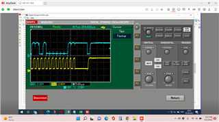
    I checked in the oscilloscope and the last valid data generated the stop bit accordingly (attached).


    Using breakpoints, I know that the program is not passing at handleNACKandTimeout or handleNACK.

    Immediately after the BB=1 occurred, I checked the registers:

    • I2CMDR and the follow bits are 1: IRS, MST, FREE.
    • I2CSTR and the follow bits are 1: NACK, ARDY, XRDY, SCD, XSMT, BB, NACKSNT.

    According to the I2C datasheet, BB is cleared by any one of the following events:

    • The I2C module receives or transmits a STOP bit (bus free).
    • The I2C module is reset.

    Questions:

    1. Please, could you give me some tips about why I’m having the BB=1 even after a proper stop bit (I2CSTR.SCD=1)?
    2. There is a way to test if the problem is being generated by the sensor (transmitter)?
    3. There is a good practice or standard which establish the success/attempt ratio in I2C communications?
    4. Could I interpret that the reduction of success/attempt ratio to 60% is related with my DSP overload? If I'm using the FIFO interruption mode to treat the data, it should not be minimized or not even exist?

    Thanks again!!!

    Andrias

  • Hi Andrias,

    I checked in the oscilloscope and the last valid data generated the stop bit accordingly (attached).

    Looks like there's a NACK in your waveform. Is that intended?

    Please, could you give me some tips about why I’m having the BB=1 even after a proper stop bit (I2CSTR.SCD=1)?

    Are you certain you're seeing BB=1 after the STOP condition occurs? Are you debugging in CCS and checking the register bit during run-time?

    There is a way to test if the problem is being generated by the sensor (transmitter)?

    Only if the sensor was holding the I2C lines low for some reason, I believe.

    • There is a good practice or standard which establish the success/attempt ratio in I2C communications?
    • Could I interpret that the reduction of success/attempt ratio to 60% is related with my DSP overload? If I'm using the FIFO interruption mode to treat the data, it should not be minimized or not even exist?

    You mention it's worse during normal run time. This makes me think your I2C code / interrupts are getting over-stepped by something else in your project. Maybe other interrupts are being serviced and the I2C ISR is not able to get serviced as quickly.

    Best,

    Kevin

  • Hi Kevin,

    Yes, I was expecting a NACK, I’m receiving 5 bytes from my sensor and according to the datasheet “In the master-receiver mode: The I2C module sends an ACK bit during each acknowledge cycle until the internal data counter counts down to 0. At that point, the I2C module sends a NACK bit to the transmitter.”

    Yes, I’m debugging using the CCS with breakpoint at the bus busy status (line 68 example file i2cLib_FIFO_interrupt.c). At that time the register I2CSTR has: I2CSTR.NACK=1, I2CSTR.SCD=1 and I2CSTR.BB=1.

    I tried to include a timeout in the checkBusStatus function so the code will wait 100 ns for the bus be free but still not working. During the entire 100 ns I2CSTR.SCD=1 (stop bit generated). Look, in my application, every 1 ms will start a new read data from my sensor. I cannot wait much longer to check if the bus is free or not.

    Well, I’m using the FIFO interrupt example expecting that DSP overload would be minimized or not even exist, it is quite disappointing that the DSP is not able to handle the few interruptions running.

    I insist, do you know any a good practice or standard which establish the success/attempt ratio in I2C communications?

    Please, do you have any suggestions about how BB=1 if SCD=1? How test what is going on with my communication using the example for F2806x from C2000WARE? Again, I didn’t change one line from the example, the only difference is that in our firmware the communication starts in a time interruption that occurs every 1 ms. Do you think I should create a separated post asking help for the example F2806x?

    I really appreciate any comments, suggestions, and tips.

    Thanks,

    Andrias

  • Hi Andrias,

    What I2C device are you interfacing with? You should match your protocol and code to the device specifications. Please note that the example I shared is for interfacing with an I2C EEPROM device. You can adapt it to your device and use the underlying functions / framework.

    Can you provide the part number for your I2C device?

    Yes, I’m debugging using the CCS with breakpoint at the bus busy status (line 68 example file i2cLib_FIFO_interrupt.c). At that time the register I2CSTR has: I2CSTR.NACK=1, I2CSTR.SCD=1 and I2CSTR.BB=1.

    BB should be cleared after a STOP condition is generated. You've confirmed that the STOP condition is actually generated on the bus with an oscilloscope when you hit this breakpoint condition? If you continue executing code for some cycles after the breakpoint do these registers bits get cleared? I'm thinking this register bit behavior may have to do with I2CMDR.FREE = 0 being configured (i.e. stop immediately when a breakpoint is hit).

    I insist, do you know any a good practice or standard which establish the success/attempt ratio in I2C communications?

    Have you clearly identified what part of your I2C comms is typically failing? Is it during the Slave Address portion, read, write, etc ? Understanding this would help.

    Do you think I should create a separated post asking help for the example F2806x?

    There's no need, I was the one who wrote and tested the example code. We can continue discussing on this thread.

    Best,

    Kevin

  • Hi Kevin,

    Yes, I changed some defines to adapt to my sensor and the TMS320F2809 I2C module:

    #define EEPROM_SLAVE_ADDRESS     0x20

    #define EEPROM_LOW_ADDR             0x2E

    #define EEPROM_DATA_BYTES           5

    #define I2C_FIFO_LEVEL                    16

    I’m using the TMS320F2809 I2C module configured in master mode, 380 kbps, RM=0 reading data from a flow sensor (5 bytes). Well, the datasheet of the flow sensor is not in English (it is attached).

    Yes, after the breakpoint I checked in the oscilloscope (screen from post on Sept 5) and I’m having a NACK and then a STOP. Even 100 ns after the breakpoint the registers still: I2CSTR.NACK=1, I2CSTR.SCD=1 and I2CSTR.BB=1.

    I’ll change the I2CMDR.FREE = 1 and see what happens. Do you have any other suggestion?

    Thank you so much,

    Andrias

    Datasheet_FlowTEX_v1_0 (1).pdf

  • Hi Andrias,

    Yes, after the breakpoint I checked in the oscilloscope (screen from post on Sept 5) and I’m having a NACK and then a STOP. Even 100 ns after the breakpoint the registers still: I2CSTR.NACK=1, I2CSTR.SCD=1 and I2CSTR.BB=1.

    This behavior doesn't make sense to me. The BB bit is 0 before the transfer begins, right?

    I'll take a look at the datasheet and let you know if I think of any other reason or thing to try.

    Best,

    Kevin

  • Hi Kevin,

    About your last question, "The BB bit is 0 before the transfer begins, right?", the answer is NO, that is my problem, BB is not 0. I’m having BB=1 even after a proper stop bit (I2CSTR.SCD=1)? I'm reporting this since my post in September 5th.

    Thank you,

    Andrias

  • Hi Andrias,

    Even 100 ns after the breakpoint the registers still: I2CSTR.NACK=1, I2CSTR.SCD=1 and I2CSTR.BB=1.

    Do the registers get cleared if you wait much longer than 100ns before stopping at a breakpoint?

    About your last question, "The BB bit is 0 before the transfer begins, right?", the answer is NO, that is my problem, BB is not 0. I’m having BB=1 even after a proper stop bit (I2CSTR.SCD=1)?

    I was meaning before any I2C transmission occurs. Do you check the BB bit to make sure it's 0 in your code before starting new communication? Starting new communication when BB=1 is only for repeated START condition cases.

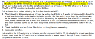
    Please see info below about BB state remaining after I2C is in reset (IRS=0). It could be that your I2C module is getting confused about the state of the bus, depending on how you handle this and things in your I2C code.

    Can you share your I2C code with me for review? If you don't feel comfortable sharing on the forum you can send over private E2E message.

    Best,

    Kevin