This thread has been locked.

If you have a related question, please click the "Ask a related question" button in the top right corner. The newly created question will be automatically linked to this question.

TMS320F28069M: CLA to clear OSHT event

Part Number: TMS320F28069M
Other Parts Discussed in Thread: C2000WARE

hi,

I have to manage OSHT event during each half pwm of 2 PWMs so, 4 interrupts to clear event.

My F28 processor is too busy to do this job without disturbing real time control loops (lagging).

So I was thinking to perform this within the CLA coprocessor.

Have you similar example reconfiguring or clearing OSHT on the fly in the CLA for a F2806x ?

Best regards

Ol

  • Hi,

    I have reached out to the experts and will let you know soon.

    Thanks,

    Ashwini

  • Hi,

    Have you similar example reconfiguring or clearing OSHT on the fly in the CLA for a F2806x ?

    We don't have any examples to showcase something like this. 

    OSHT flag is cleared by just clearing the bit. Something like the below. You can try including this within your CLA task. 

    EALLOW;

    EPwm1Regs.TZCLR.bit.OST = 1;

    EDIS;


    Best Regards,

    Marlyn

  • Thanks for your answer Marlyn.

    I managed many times OST in F28 CPU and able to clear it but never do it in the CLA.

    How to execute CLA TASK1 on OST Event ?

    Best regards,

    Ol

  • Hi,

    I don't believe there is a way to trigger a CLA task based on an OST event. What is your current trigger source for the CLA task?

    Best Regards,

    Marlyn

  • Hi Marlyn,

    I think i will trigger the task using PWMINT and test if event occurred and then clear it at the right time.

    But without example, i spent lot of time to discover how to perform it.

    Regards,

    Ol

  • Hi OI,

    But without example, i spent lot of time to discover how to perform it.

    Unfortunately we do not have any examples that showcase this particular task. 

    All of the software examples we have are within: C:\ti\c2000\C2000Ware_version\device_support\f2806x

    Best Regards,

    Marlyn

  • Hi Marlyn

    I found calculation examples Sin, Exp and matrix or ADC event but no example using PWM as trigger.

    do I have to generate the interrupt from the CPU to start a ClaTask - TASK4 (for example) or can the IT be generated directly from the CLA ?

    I use already PWM4 in the CPU to generate INT and my idea is to generate an INDEPENDANT IT in the CLA to reset OST event.

    So, I set EPWM4INT interrupt in MPISRCSEL1 register to start (execute) Cla1Task4.

    Task4 is never executed becaus i place  "__mdebugstop(); " and code never stop on it even if I place a breakpoint.

    There is something to set in the main cpu code other than InitCla() ?

    Regards,

    OL

    File ClaTasks_C.cla

    /**********************************************************************
    * Task: CLA Task 4
    **********************************************************************/
    __interrupt void Cla1Task4 (void)
    {
        

        __mdebugstop();
    }

    **********************************************************************

    File Cla_10.c

    InitCla

        asm(" EALLOW");                     // Enable EALLOW protected register access

    //--- Memory Configuration
    //    Cla1Regs.MMEMCFG.bit.PROGE = 1;     // Configure as CLA program memory
    //    Cla1Regs.MMEMCFG.bit.RAM1E = 1;     // Configure as CLA data memory (C compiler scratchpad)

    //--- Initialize CLA task interrupt vectors (symbols used to calculate vector address)

        //Cla1Regs.MVECT1 = (Uint16) (&Cla1Task1 - &Cla1Prog_Start)*sizeof(Uint32);

        Cla1Regs.MVECT1 = (Uint16)((Uint32)&Cla1Task1 - (Uint32)&Cla1Prog_Start);
        Cla1Regs.MVECT2 = (Uint16)((Uint32)&Cla1Task2 - (Uint32)&Cla1Prog_Start);
        Cla1Regs.MVECT3 = (Uint16)((Uint32)&Cla1Task3 - (Uint32)&Cla1Prog_Start);
        Cla1Regs.MVECT4 = (Uint16)((Uint32)&Cla1Task4 - (Uint32)&Cla1Prog_Start);
        Cla1Regs.MVECT5 = (Uint16)((Uint32)&Cla1Task5 - (Uint32)&Cla1Prog_Start);
        Cla1Regs.MVECT6 = (Uint16)((Uint32)&Cla1Task6 - (Uint32)&Cla1Prog_Start);
        Cla1Regs.MVECT7 = (Uint16)((Uint32)&Cla1Task7 - (Uint32)&Cla1Prog_Start);
        Cla1Regs.MVECT8 = (Uint16)((Uint32)&Cla1Task8 - (Uint32)&Cla1Prog_Start);

    //--- Select Task interrupt sources
        Cla1Regs.MPISRCSEL1.bit.PERINT1SEL = 1;    // 0=ADCINT1    1=none    2=EPWM1INT
        Cla1Regs.MPISRCSEL1.bit.PERINT2SEL = 1;    // 0=ADCINT2    1=none    2=EPWM2INT
        Cla1Regs.MPISRCSEL1.bit.PERINT3SEL = 1;    // 0=ADCINT3    1=none    2=EPWM3INT
        Cla1Regs.MPISRCSEL1.bit.PERINT4SEL = 2;    // 0=ADCINT4    1=none    2=EPWM4INT
        Cla1Regs.MPISRCSEL1.bit.PERINT5SEL = 1;    // 0=ADCINT5    1=none    2=EPWM5INT
        Cla1Regs.MPISRCSEL1.bit.PERINT6SEL = 1;    // 0=ADCINT6    1=none    2=EPWM6INT
        Cla1Regs.MPISRCSEL1.bit.PERINT7SEL = 1;    // 0=ADCINT7    1=none    2=EPWM7INT
        Cla1Regs.MPISRCSEL1.bit.PERINT8SEL = 1;    // 0=ADCINT8    1=none    2=CPU Timer

        Cla1Regs.MICLROVF.all           =    0xFF;
        Cla1Regs.MIER.bit.INT4          =    1;     // Enable Task1


        //
        // Copy the CLA program code from its load address to the CLA program
        // memory. Once done, assign the program memory to the CLA
        //
        // Make sure there are at least two SYSCLKOUT cycles between assigning
        // the memory to the CLA and when an interrupt comes in
        //
        memcpy(&Cla1funcsRunStart, &Cla1funcsLoadStart, (Uint32)&Cla1funcsLoadSize);

       // Cla1Regs.MMEMCFG.bit.PROGE = 1;
       // Cla1Regs.MMEMCFG.bit.RAM0E = 1;

        //
        // Enable the IACK instruction to start a task
        // Enable the CLA interrupt 8 and interrupt 7

        Cla1Regs.MCTL.bit.IACKE = 1;

  • Hi,

    I don't see anything incorrect with the setup. To help debug this can you try/confirm he following:

    1. If you use software trigger to start task, does that work? This was we can root cause if the issue is with the EPWM trigger or CLA setup

    2. I assume you are able to see the C28 interrupt routine being executed when EPWM triggers but not CLA task

    Thanks,
    Ashwini

  • Hi Ashwini,

    Thanks for your answer.

    1. I don't use software trigger to start task. How can i do it ?

    2. Exact I can monitor easily what append on F28CPU but nothing on CLA Task. So, i added LED toggle such as

    interrupt void Cla1Task1 (void)
    {
        ClaISR++; // = ClaISR + 1;
        if(ClaISR > 1000000){
            GpioDataRegs.GPBTOGGLE.bit.GPIO34 = 1;
            ClaISR = 0;
            //__mdebugstop();
        }

    If I use __mdebugstop(); CCS always stops on it but GPIO never changes state and ClaISR never change too. So that means TASK seems to be properly activated but the instructions are not taken into account. However, I have a doubt about execution because if i place __mdebugstop in other tasks never called and without trigger, CCS stop also. CLA is exhausting me...

    If you have ideas or tests, they are welcome.

    Regards

    OL

  • Hi,

    I worked on and I remove GPIO control within the Cla TASK, I read it is not allowed/accessible for F28069 chip.

    After research, I finally found the DCL library with examples for the F28069. I added also dcl.h and cla_shared.h found in /ti/C2000Ware/C2000Ware_4_00_00_00/examples/DCL/F28069_DF23_CLA

    By retrieving the files from DCL to my project and studying the sample files, now I can see in CCS debugger my variable ClaISR changing. After many errors and bad files issues, it finally works.

    How can i change state of a GPIO if register is not accessible ? I could use a PWM as discussed in the forum but unfortunately i already use all pwm outputs.

    Any idea ?

    Regards,

    OL

  • Hi OL,

    The state of GPIO cannot be changed by CLA. What is the purpose of toggling the GPIO?

    Thanks,

    Ashwini

  • Hi Ashwini,

    The purpose is to know the exact position of the cla task regarding PWMs.

    If i want to synchrone even from several PWM it is easyto use GPIO to have position of event and be able to perform an action just at the right moment.

    Regards,

    OL

  • Hi OL,

    Sorry for the late reply, TI had a holiday for labor day. I will reach out to the team to see if there are other options here since GPIO is not accessible by CLA.

    Thanks,
    Ashwini

  • Hi Ashwini,

    I used PWM8 to change CMPA from 0 to PRD and PRD to 0 diring task to have a simple debug . It seems to work.

    But....

    New problem.. As explained previously I have two tasks: TASK 4 and TASK 5 corresponding to an interruption at the period of PWM4 and PWM5. For PWM4 no problem I see task4 count variable moving but nothing for PWM5. It doesn't work while I have the same configuration.

    When I forc TASK using Cla1Regs.MIFRC.bit. INT4 or INT5 or INT8 it work correctly and I can saw variables in tasks changing but there is only INT4 working auto and autonomously.

    Please help me I spent already many many time to debug it. It's too too long

    regards,

    Ol

  • void InitCla(void)
    {
    asm(" EALLOW"); // Enable EALLOW protected register access

    //--- Memory Configuration
    // Cla1Regs.MMEMCFG.bit.PROGE = 1; // Configure as CLA program memory
    // Cla1Regs.MMEMCFG.bit.RAM1E = 1; // Configure as CLA data memory (C compiler scratchpad)

    //--- Initialize CLA task interrupt vectors (symbols used to calculate vector address)

    // Cla1Regs.MVECT4 = (Uint16) (&Cla1Task1 - &Cla1Prog_Start)*sizeof(Uint32);

    Cla1Regs.MVECT1 = (Uint16)((Uint32)&Cla1Task1 - (Uint32)&Cla1Prog_Start);
    Cla1Regs.MVECT2 = (Uint16)((Uint32)&Cla1Task2 - (Uint32)&Cla1Prog_Start);
    Cla1Regs.MVECT3 = (Uint16)((Uint32)&Cla1Task3 - (Uint32)&Cla1Prog_Start);
    Cla1Regs.MVECT4 = (Uint16)((Uint32)&Cla1Task4 - (Uint32)&Cla1Prog_Start);
    Cla1Regs.MVECT5 = (Uint16)((Uint32)&Cla1Task5 - (Uint32)&Cla1Prog_Start);
    Cla1Regs.MVECT6 = (Uint16)((Uint32)&Cla1Task6 - (Uint32)&Cla1Prog_Start);
    Cla1Regs.MVECT7 = (Uint16)((Uint32)&Cla1Task7 - (Uint32)&Cla1Prog_Start);
    Cla1Regs.MVECT8 = (Uint16)((Uint32)&Cla1Task8 - (Uint32)&Cla1Prog_Start);

    //--- Select Task interrupt sources
    Cla1Regs.MPISRCSEL1.bit.PERINT1SEL = 1; // 0=ADCINT1 1=none 2=EPWM1INT
    Cla1Regs.MPISRCSEL1.bit.PERINT2SEL = 1; // 0=ADCINT2 1=none 2=EPWM2INT
    Cla1Regs.MPISRCSEL1.bit.PERINT3SEL = 1; // 0=ADCINT3 1=none 2=EPWM3INT
    Cla1Regs.MPISRCSEL1.bit.PERINT4SEL = 2; // 0=ADCINT4 1=none 2=EPWM4INT
    Cla1Regs.MPISRCSEL1.bit.PERINT5SEL = 2; // 0=ADCINT5 1=none 2=EPWM5INT
    Cla1Regs.MPISRCSEL1.bit.PERINT6SEL = 1; // 0=ADCINT6 1=none 2=EPWM6INT
    Cla1Regs.MPISRCSEL1.bit.PERINT7SEL = 1; // 0=ADCINT7 1=none 2=EPWM7INT
    Cla1Regs.MPISRCSEL1.bit.PERINT8SEL = 1; // 0=ADCINT8 1=none 2=CPU Timer

    // Enable the IACK instruction to start a task
    // Enable the CLA interrupt 8 and interrupt 7
    Cla1Regs.MCTL.bit.IACKE = 1;

    Cla1Regs.MICLROVF.all = 0xFFFF;


    //
    // Copy the CLA program code from its load address to the CLA program
    // memory. Once done, assign the program memory to the CLA
    //
    // Make sure there are at least two SYSCLKOUT cycles between assigning
    // the memory to the CLA and when an interrupt comes in
    //
    memcpy(&Cla1funcsRunStart, &Cla1funcsLoadStart, (Uint32)&Cla1funcsLoadSize);

    Cla1Regs.MMEMCFG.bit.PROGE = 1;
    // Cla1Regs.MMEMCFG.bit.RAM0E = 1;

    Cla1Regs.MIER.all = (M_INT4 | M_INT5 | M_INT8);

    //Cla1Regs.MIER.bit.INT4 = 1; // Enable Task1
    //Cla1Regs.MIER.bit.INT5 = 1; // Enable Task2


    //Cla1Task8();

    Cla1Regs.MIFRC.bit.INT8 = 1;

    asm("EDIS");

    } // end of InitCla()

  • /**********************************************************************
    * File: ClaTasks.cla
    * Devices: TMS320F2806x
    * Author: Technical Training Organization (TTO), Texas Instruments
    **********************************************************************/

    /*********************************************************************
    * Include header files, constants, and variables used in CLA C code.
    * Note: included here rather than referencing Lab.h to avoid conflicts
    * with features not supported by the CLA C compiler.
    **********************************************************************/

    #include "F2806x_Cla_typedefs.h"
    #include "F2806x_Device.h"
    #include "cla_shared.h"

    //#define FILTER_LEN 5
    //extern float32 xDelay[FILTER_LEN];
    //extern float32 coeffs[FILTER_LEN];
    //extern Uint16 ClaFilteredOutput;

    extern Uint16 Cla1Prog_Start;
    //Uint32 ClaISR;


    #if 1 // 1 = Use Task1 from this file; 0 = Don't use
    /**********************************************************************
    * Task: CLA Task 1
    *
    * This task is triggered at the end of conversion with an ADC interrupt.
    * The ADC RESULT0 register is read as soon as it is available. It will then
    * run a FIR filter and places the result into ClaFilter. The CPU will take
    * an interrupt at the end of the task. It will log the ADC RESULT0 register
    * for comparison as well as the CLA generated ClaFilter value.
    **********************************************************************/
    __interrupt void Cla1Task1 (void)
    {
    //__mdebugstop();

    }
    #endif
    /**********************************************************************
    * Task: CLA Task 2
    **********************************************************************/
    __interrupt void Cla1Task2 (void)
    {
    //ClaISR2++; // = ClaISR + 1;
    //__mdebugstop();
    }
    /**********************************************************************
    * Task: CLA Task 3
    **********************************************************************/
    __interrupt void Cla1Task3 (void)
    {
    //__mdebugstop();
    }

    /**********************************************************************
    * Task: CLA Task 4
    **********************************************************************/
    __interrupt void Cla1Task4 (void)
    {
    ClaISR++; // = ClaISR + 1;

    __meallow();
    Cla1Regs.MICLR.bit.INT4 = 1;
    //ClaISRR++;
    //__mdebugstop();

    if(EPwm8Regs.CMPA.half.CMPA > 0)
    EPwm8Regs.CMPA.half.CMPA = 0;
    else
    EPwm8Regs.CMPA.half.CMPA = 113;


    __medis();

    //Cla1ForceTask4();
    }

    /**********************************************************************
    * Task: CLA Task 5
    **********************************************************************/
    __interrupt void Cla1Task5 (void)
    {
    ClaISRR++;
    //__mdebugstop();
    __meallow();
    Cla1Regs.MICLR.bit.INT5 = 1;
    __medis();

    //Cla1ForceTask5();
    }
    /**********************************************************************
    * Task: CLA Task 6
    **********************************************************************/
    __interrupt void Cla1Task6 (void)
    {
    //__mdebugstop();
    }
    /**********************************************************************
    * Task: CLA Task 7
    **********************************************************************/
    __interrupt void Cla1Task7 (void)
    {
    //__mdebugstop();
    }
    /**********************************************************************
    * Task: CLA Task 8
    *
    * The delay elements xDelay are placed in the section ClaToCpuMsgRAM.
    * The C28x does not have write access to this array. Therefore, this
    * array will not be initialized at startup time by the cinit routine.
    * The purpose of this task is to do a one-time initialization of the
    * delay buffer and set the elements to zero.
    **********************************************************************/
    __interrupt void Cla1Task8 (void)
    {
    // Local Variables
    //int16 i;

    ClaISR = 0;
    ClaISRR = 0;

    //__mdebugstop();

    /* for(i = 0; i < 5; i++)
    {
    xDelay[i] = 0.0;
    }*/

    //Cla1ForceTask8();
    }

    //--- end of file -----------------------------------------------------

  • but nothing for PWM5.

    I don't see anything in the CLA configuration that may be causing this. Can you set a breakpoint after InitCla is complete and take a look at CLA configuration registers in CCS registers window to check that the register configuration looks correct. Also can you setup the EPWM5 to trigger the C28 CPU - this will ensure that EPWM5 configuration is correct and is indeed generating a trigger.

    Cla1Regs.MICLR.bit.INT5 = 1;

    Why is the task doing this, the INT5 is cleared automatically when task is entered. Also this register is accessible by C28 CPU only and CLA task cannot write to it.

    Thanks,

    Ashwini

  • Hi Ashwini,

    Thank you for your answer.

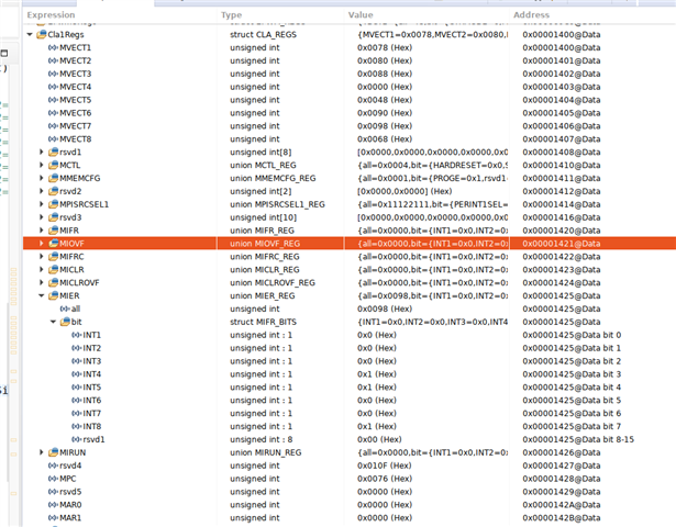
    take a look at CLA configuration registers in CCS registers window to check that the register configuration looks correct.

    It seems to be ok.

    Also can you setup the EPWM5 to trigger the C28 CPU - this will ensure that EPWM5 configuration is correct and is indeed generating a trigger.

    I perform it in the main code setup.

        EPwm5Regs.ETSEL.bit.INTSEL     = ET_CTR_ZERO;    // ET_CTRU_CMPA;        // INT on CMPA event : Enable event time-base counter equal to CMPA when the timer is incrementing.
        EPwm5Regs.ETSEL.bit.INTEN     = 1;            // Enable INT
        EPwm5Regs.ETPS.bit.INTPRD     = ET_1ST;        // Generate INT every event

    It is what you suggested ?

    Why is the task doing this, the INT5 is cleared automatically when task is entered.

    It were just for testing if there is a action. I removed it.

    Regards,

    Ol

  • Here under initialisation of CPU interrupt. I cheeked INT1 and INT4 work. INT5 is not enable.

    //=================================================================================
    // INTERRUPT & ISR INITIALISATION (best to run this section after other initialisation)
    //=================================================================================
    //Also Set the appropriate # define's in the {ProjectName}-Settings.h
    //to enable interrupt management in the ISR
    EALLOW;
    PieVectTable.EPWM1_INT = &MainISR; // IT sur 20 kHz
    PieVectTable.EPWM4_INT = &DPL_ISR; //

    PieVectTable.EPWM1_TZINT = &epwm1_tz3_int_isr; // TZ3 ONE SHOT

    //--------------------------------------------------------------------------------------------
    PieCtrlRegs.PIEIER3.bit.INTx1 = PWM1_INT_ENABLE; //Interrupt

    EPwm1Regs.ETSEL.bit.INTEN = 1; // Enable EPWM1INT generation
    EPwm1Regs.ETSEL.bit.INTSEL = ET_CTR_ZERO; // Enable interrupt CNT_zero event
    EPwm1Regs.ETPS.bit.INTPRD = ET_1ST; // Generate interrupt on the 1st event
    EPwm1Regs.ETCLR.bit.INT = 1; // Enable more interrupts
    //--------------------------------------------------------------------------------------------

    PieCtrlRegs.PIEIER3.bit.INTx4 = PWM4_INT_ENABLE; // PIE level enable, Grp3 / Int1

    EPwm4Regs.ETSEL.bit.INTSEL = ET_CTR_ZERO; // ET_CTRU_CMPA;
    EPwm4Regs.ETSEL.bit.INTEN = 1; // Enable INT
    EPwm4Regs.ETPS.bit.INTPRD = ET_1ST; // Generate INT every event
    //--------------------------------------------------------------------------------------------

    //PieCtrlRegs.PIEIER3.bit.INTx5 = PWM5_INT_ENABLE; // PIE level enable, Grp3 / Int1

    EPwm5Regs.ETSEL.bit.INTSEL = ET_CTR_ZERO;
    EPwm5Regs.ETSEL.bit.INTEN = 1; // Enable INT
    EPwm5Regs.ETPS.bit.INTPRD = ET_1ST; // Generate INT every event

    // Enable Peripheral, global Ints and higher priority real-time debug events:
    IER |= M_INT3; /* Main IT */
    IER |= M_INT2; /* TZ PWM4 ou TZ PWM5 ou TZ PWM1 IT */

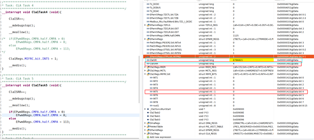
  • ClaISR variable is declared as CLAtoCPU used in TASK4 (PWM4INT) and it is running automatically every PWM4 period. ClaISR is incremented. I saw it in CCS watch window. 

    ClaISRR variable is also declared as CLAtoCPU and used in TASK5 (PWM5INT) but it is not running.

    If i use Force INT5, ClaISRR variable is properly incremented but the task5 is not trigger as interrupt.

    If I make de test with this line in TASK4 to start INT5 Cla1Regs.MIFRC.bit.INT5 = 1;

    It doesn't start too.

    TASK5 is executed ONLY if I FORCE interrupt in CCS Wtach windows.

    Whey TASK5 is not triggered by PWM5INT ??

  • I set CLAINT4 and 5 feedback interrupts in CPU such as

        PieVectTable.CLA1_INT4 = &Cla1Task4_ISR_FEEDBACK;
        PieCtrlRegs.PIEIER11.bit.INTx4 = 1;

        PieVectTable.CLA1_INT5 = &Cla1Task5_ISR_FEEDBACK;
        PieCtrlRegs.PIEIER11.bit.INTx5 = 1;

    Only Cnt_CLA_TASK4_FEEDBACK counter change so only TASK4 give e feebback TASK5 is clearly not executed


    __interrupt void Cla1Task4_ISR_FEEDBACK(void){

        Cnt_CLA_TASK4_FEEDBACK++;

        PieCtrlRegs.PIEACK.all = PIEACK_GROUP11;  /* set breakpointer here*/
    }

    __interrupt void Cla1Task5_ISR_FEEDBACK(void){

        Cnt_CLA_TASK5_FEEDBACK++;

        PieCtrlRegs.PIEACK.all = PIEACK_GROUP11;  /* set breakpointer here*/
    }

  • Hi,

    I did a lot of testing this evening and found that to get the CLA task executed the IT in the CPU must be enabled as follows:

        PieVectTable.EPWM2_INT          = &MainISR2;             // IT sur 20 kHz
        PieCtrlRegs.PIEIER3.bit.INTx2     = PWM2_INT_ENABLE;    //Interruption sur PWM2 40 kHz

        EPwm2Regs.ETSEL.bit.INTEN     = 1;               // Enable EPWM2INT generation
        EPwm2Regs.ETSEL.bit.INTSEL     = ET_CTR_ZERO;  // Enable interrupt CNT_zero event
        EPwm2Regs.ETPS.bit.INTPRD     = ET_1ST;       // Generate interrupt on the 1st event
        EPwm2Regs.ETCLR.bit.INT     = 1;            // Enable more interrupts

        PieVectTable.EPWM3_INT          = &MainISR3;             // IT sur 20 kHz
        PieCtrlRegs.PIEIER3.bit.INTx3 = 1
        EPwm3Regs.ETSEL.bit.INTEN     = 1;               // Enable EPWM3INT generation
        EPwm3Regs.ETSEL.bit.INTSEL     = ET_CTR_ZERO;  // Enable interrupt CNT_zero event
        EPwm3Regs.ETPS.bit.INTPRD     = ET_1ST;       // Generate interrupt on the 1st event

    I tried with PWM2 and 3 which did not work and now the TASKS of the CLA are executed.

    Monday morning I'll try with the PWM5 but it's sure to be the same.

    I had understood that the CPU and the CLA were independent for once I no longer understand.
    In addition there is no point in having an IT on both CPUs it's a waste of time.

    Must we declare an IT on the CPU side for the CLA to work?
    Could be a DMA bug?


    Thank you for your help.

    Ol

  • Hi,

    I did a lot of testing this evening and found that to get the CLA task executed the IT in the CPU must be enabled as follows:

    Can you point to the specific source line in the code snippet you shared that you had to add to get "IT in the CPU" enabled which led to CLA task execution?

    I had understood that the CPU and the CLA were independent for once I no longer understand.

    That is correct, they are independent. The interrupt can be setup to trigger either the C28 or CLA and does not have to do both.

    Thanks,

    Ashwini

  • hi,

    What I observed is that I have to activate the IT of the CPU so that it is effective in the CLA.

    The reason why PWM5 was not working in the CLA, was that it was not enabled in the CPU while PWM4 was enabled in the CPU and running as can be seen from the code snippet provided. I also tried with the other PWMs (1 and 2) and it reacts (responds) exactly by the same way. The Interrupt must be enabled and running in the CPU for it to be used in the CLA.... I do not understand why.

    That is correct, they are independent. The interrupt can be setup to trigger either the C28 or CLA and does not have to do both.

    Clearly not in my code. PWM4A is the main IT of my prog at the period. I have both enabled (PWM4 INT) in CPU and also in the CLA at the same time and it works.

    Why do I have to activate the CPU IT to make the CLA IT work ?

    Regards,

    Olivier

  • Someone able to help me at tech support or should I change µc ? It's been more than 23 days that I have the same problem really thank you thanks a lot for the help

  • I take an example of F28069 using adc and I added CLAtask3 ie PWM3INT .

    I also added INT3 in the F28CPU to get feedback.

    With ADC it works

    With PWMINT3 it doesn't work !

    Please let me know if you see something that's crazy