This thread has been locked.

If you have a related question, please click the "Ask a related question" button in the top right corner. The newly created question will be automatically linked to this question.

TMS320F28375S: Code behaves incorrectly after reset

Part Number: TMS320F28375S
Other Parts Discussed in Thread: LAUNCHXL-F28379D, C2000WARE, TMS320F28379D

Hi,

I was working on a board with TMS320F28375S. Code was executing as intended even after the resets (Soft and Power on both).

I switched to a different board which is supposed to be the copy of the previous board, and the same code does not execute correctly after resets (for both soft and power on reset). Part of the application runs fine, like I could see CAN communication happening and few other calculations. Part of my code runs from CLA. It reads motor position and speed from Resolver chip on SPI bus. This part of the code starts giving incorrect speed values. If I run with debugger connected (without power cycle), it runs fine. But as soon as I do a soft reset or a power cycle, it gives incorrect speed values.

Another observation is many of the variables show "NaN" when I click on run after the reset. Some of them change back to good values after few moments. Resolver speed gets set to "inf" and remains there. I could also see some of the RAMGS0 memory (starting from 0xC000) initialised to 0xFFFF. This memory has .ebss section mapped against it. All this does not happen if I program and run with debugger connected.

I tried the same code on LaunchXL-F28379D, it works OK on this launchpad.

I assume Boot mode settings should be fine as I could see CAN comms working. I checked GPIO72 is 1, GPIO84 is 1, OTP for bootctrl is not programmed.

Could you please suggest any checks that I can do either hardware or software to debug this problem?

Thank you.

  • Hi, 

    It looks like problem occurred because RAM was initialised to 0xFFFF by BOOT ROM code. My code had some global variables which had zero initial values were also initialised to 0xFFFF and calculations were going wrong from that point.

    I have added the initialisation of those variables in a function and my problem is resolved for now, but I am wondering why I did not see this issue in the LaunchXL-F28379D and my previous board with the same microcontroller. Is there a difference in the boot rom code for different parts?

    Thank you.

  • No, the boot-ROM code is exactly identical. The only difference appears to be that you are using a single-core device but the LaunchPad uses a dual-core device.

    Note, however, that not all resets are treated the same way. What the boot-ROM does is dependent on the type of reset (Refer to Table 4-7. Boot ROM Reset Causes and Actions in page 570 of www.ti.com/lit/SPRUHX5). Specifically, RAM initialization is not done for certain type of resets. One more thing you may want to look into is whether you have initialized constants in RAM. See https://e2e.ti.com/support/microcontrollers/c2000/f/171/t/757590 for debug tips. Admittedly, it is for a different device family, but the debug tips are valid for your device as well.

  • I had also tried the same code on two different boards and both the boards had TMS320F28375S microcontrollers. It was working fine on the first microcontrollers from nearly 2 years. The problem appeared only when I switched to the second board. That is why I thought BOOT ROM code might be different. Also I tried both soft reset using debugger and the power cycle. I was seeing the same result.

    Thank you for the suggested links and the reply.

  • There were two revisions of the boot-ROM. Please see C:\ti\c2000\C2000Ware_4_01_00_00\libraries\boot_rom\f2837xs. The boot-ROM version information is available at 0x003FFF7A. However, if your silicon version is the same, then your Boot-ROM version is also the same. The only other reason I can think of is some initialized constant being loaded in RAM as mentioned in my previous post. If you do find the root-cause of the issue, please let us know. I will close the post.

  • Hi Hareesh,

    I just found that the problem still exists after initialisation code. Initialisation just resolved the problem for that variable. 

    The SPI code does not work correctly after a reset. It reads incorrect values from an external chip (AD2S1210). Instead of shuffling between 0x0 (0) and 0xFFFF (-1), it shuffles between 0x0 (0) and 0x3FFF (16383). 

    The SPI read() function runs from CLA task.

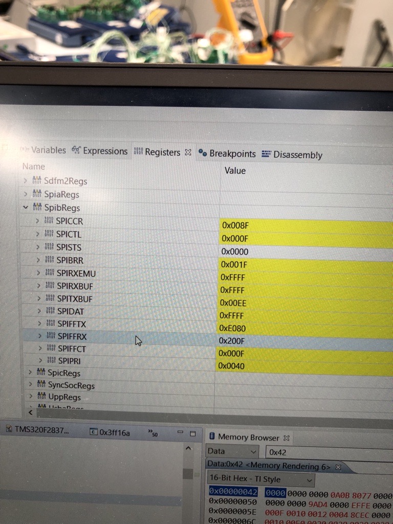
  • I observed some differences in SPI configuration registers before the SPI initialisation starts.

    If debugger is connected, below are the values just before SPI initialisation:

    If I do a reset and put a break point at the same point (Just before SPI intialisation), I see the values of SPI registers are different. SPI registers get these values before it even reaches _c_int00 symbol, so it seems it is done by boot code within the chip?

    Also, this problem does NOT occur on the Eval Card with TMS320F28379D. It only occurs on one of the board with TMS320F28375S. On another board with TMS320F28375S, it works fine.

  • Looking at the second screen shot in previous message, it even sets a reserved bit in SPIPRI register. There is something not right here.

  • Gobind,

                    It is extremely difficult to debug such problems remotely, without access to the schematics & the hardware, thorough knowledge of the application code and the sequence of events. I can provide some debug ideas but may be unable to help beyond that. 

    Anytime there is a difference in the behavior with or without the JTAG connector connected, it almost always points to initialized constants being loaded in RAM. You can check for their presence by examining your .map file. The reason the SPI registers appear to have values before it even reaches _c_int00 symbol could be because of the SPI bootloader executed by the boot-ROM.

  • I have the below text in my cmd file. I think these will put all the declared constants in the flash. I have not put any constants manually (using pragmas) to any of the sections. So all constants in Flash.

    /* Initalized sections go in Flash */
    .econst : >> FLASHF | FLASHG | FLASHH PAGE = 0, ALIGN(4)

    Second point is the SPI. I am looking at the SPI-B module. In the reference manual, it says, the boot rom only uses the first instance of the device. So, if boot-ROM executed SPI bootloader, it should have been with SPI-A module. 

    Thanks for helping Hareesh, I understand it is difficult to debug in forum. I am just trying find some ideas for debugging.

    Thank you.

  • So, if boot-ROM executed SPI bootloader, it should have been with SPI-A module. 

    Yes, you are correct.

    At reset, clock to all peripherals come up disabled. Until your code turns on the clock as part of system initialization, all peripheral registers should only read 0x0000. One area to check would be the boot-mode-select pins; whether the pins are driven correctly (a stable/clean input at the right level - either 0v or 3.3v without any noise) when the boot-ROM takes a snapshot of these pins.

  • As you mentioned in previous replies, I checked the boot-ROM version on both F28375S cards, and they both read "0101 0114" in memory browser (16-bit hex TI style). So that is not the difference.

    I checked the GPIO DATA register for both the boot pins (GPIO84 and GPIO72) after the reset, they both stay high (no fluctuation), on both the cards. I did not measure the voltage on a multimeter, but I can do that if needed. 

    I also checked the boot-ROM status location for the card that does not work correctly. I read 0xD at location 0x00002C. It means boot-ROM handled HWBIST reset. This was mentioned in TRM (spruhx5g) section 4.10.10.1. Is this something to look out for? I did not check this for the card that works OK. 

  • I did not measure the voltage on a multimeter, but I can do that if needed. 

    No, a multimeter is not suitable. You need to measure with an oscilloscope. All that we are trying to do is to ensure the boot-mode-select pins maintain their level cleanly and for the required time.

    Will check on HWBIST

  • Gobind,

       Any update on this? 

    Have you looked into Emulation boot? The behavior of the boot-ROM is different based on whether the JTAG connector is connected (with CCS having control of the device) or not. In the case of the former, the boot-mode is selected not by the boot-mode-select pins but by the values stored in 0xD00 and 0xD01 of RAM. In the case of latter, the boot mode is indeed selected by the boot-mode pins.

    Also, how did you infer the value to be 0xD in 0x00002C?