This thread has been locked.

If you have a related question, please click the "Ask a related question" button in the top right corner. The newly created question will be automatically linked to this question.

TMDSDOCK28335: connect issue in CCS

Part Number: TMDSDOCK28335
Other Parts Discussed in Thread: CONTROLSUITE, C2000WARE

Hi teams,

    Good day!

   My customer test TMDSDOCK28335 with CCS , but there is connect issue, He have followed the EVM user guide to set the hardware . Could you kindly help to check and suggest us how to resolve the issue?

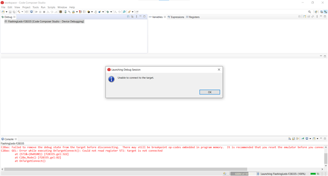
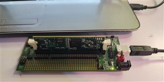
" The issue is that when the EVM board is powered and LD1 on board glows the same does not happen on the control card. The LED on the control card is not glowing and sometimes it does glow momentarily after powering the board and then goes off. The XDS100 is displayed in device manager on connecting the board which means drivers are properly installed. When I try to run a sample project through CCS, on clicking the debug button it says "unable to connect to target". 

Best Regards
Miao Bai
   

  • Hi Miao,

    Are you running any example or you are launching target configuration manually?

    Can you open the target configuration, and run 'Test Connection' and send the console log? That will help in narrowing the issue.

    Thanks & Regards,

    Santosh

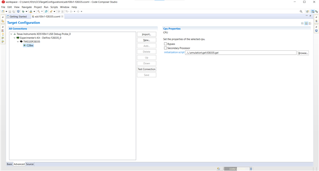
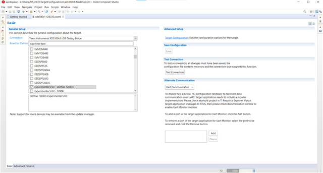
  • I am doing as mentioned in SPRUFR5I document . I have created a new target configuration as mentioned in section 4. Further I am trying to run sample program of flashing led given control suite. On running test connection I am getting the following result:

    [Start: Texas Instruments XDS100v1 USB Debug Probe_0]

    Execute the command:

    %ccs_base%/common/uscif/dbgjtag -f %boarddatafile% -rv -o -F inform,logfile=yes -S pathlength -S integrity

    [Result]


    -----[Print the board config pathname(s)]------------------------------------

    C:\Users\10\AppData\Local\TEXASI~1\CCS\ccs1040\
    0\0\BrdDat\testBoard.dat

    -----[Print the reset-command software log-file]-----------------------------

    This utility has selected a 100- or 510-class product.
    This utility will load the adapter 'jioserdesusb.dll'.
    The library build date was 'May 7 2020'.
    The library build time was '21:10:18'.
    The library package version is '9.2.0.00002'.
    The library component version is '35.35.0.0'.
    The controller does not use a programmable FPGA.
    The controller has a version number of '4' (0x00000004).
    The controller has an insertion length of '0' (0x00000000).
    This utility will attempt to reset the controller.
    This utility has successfully reset the controller.

    -----[Print the reset-command hardware log-file]-----------------------------

    The scan-path will be reset by toggling the JTAG TRST signal.
    The controller is the FTDI FT2232 with USB interface.
    The link from controller to target is direct (without cable).
    The software is configured for FTDI FT2232 features.
    The controller cannot monitor the value on the EMU[0] pin.
    The controller cannot monitor the value on the EMU[1] pin.
    The controller cannot control the timing on output pins.
    The controller cannot control the timing on input pins.
    The scan-path link-delay has been set to exactly '0' (0x0000).

    -----[The log-file for the JTAG TCLK output generated from the PLL]----------

    There is no hardware for programming the JTAG TCLK frequency.

    -----[Measure the source and frequency of the final JTAG TCLKR input]--------

    There is no hardware for measuring the JTAG TCLK frequency.

    -----[Perform the standard path-length test on the JTAG IR and DR]-----------

    This path-length test uses blocks of 64 32-bit words.

    The test for the JTAG IR instruction path-length failed.
    The many-ones then many-zeros tested length was -2002 bits.
    The many-zeros then many-ones tested length was 38 bits.

    The test for the JTAG DR bypass path-length failed.
    The many-ones then many-zeros tested length was -2048 bits.
    The many-zeros then many-ones tested length was 32 bits.

    -----[Perform the Integrity scan-test on the JTAG IR]------------------------

    This test will use blocks of 64 32-bit words.
    This test will be applied just once.

    Do a test using 0xFFFFFFFF.
    Test 1 Word 0: scanned out 0xFFFFFFFF and scanned in 0x00000001.
    Test 1 Word 1: scanned out 0xFFFFFFFF and scanned in 0x00000000.
    Test 1 Word 2: scanned out 0xFFFFFFFF and scanned in 0x00000000.
    Test 1 Word 3: scanned out 0xFFFFFFFF and scanned in 0xFFFC0000.
    Test 1 Word 5: scanned out 0xFFFFFFFF and scanned in 0x0000FFFF.
    Test 1 Word 6: scanned out 0xFFFFFFFF and scanned in 0x00000000.
    Test 1 Word 7: scanned out 0xFFFFFFFF and scanned in 0x00000000.
    Test 1 Word 8: scanned out 0xFFFFFFFF and scanned in 0xE0000000.
    The details of the first 8 errors have been provided.
    The utility will now report only the count of failed tests.
    Scan tests: 1, skipped: 0, failed: 1
    Do a test using 0x00000000.
    Scan tests: 2, skipped: 0, failed: 1
    Do a test using 0xFE03E0E2.
    Scan tests: 3, skipped: 0, failed: 2
    Do a test using 0x01FC1F1D.
    Scan tests: 4, skipped: 0, failed: 3
    Do a test using 0x5533CCAA.
    Scan tests: 5, skipped: 0, failed: 4
    Do a test using 0xAACC3355.
    Scan tests: 6, skipped: 0, failed: 5
    Some of the values were corrupted - 80.5 percent.

    The JTAG IR Integrity scan-test has failed.

    -----[Perform the Integrity scan-test on the JTAG DR]------------------------

    This test will use blocks of 64 32-bit words.
    This test will be applied just once.

    Do a test using 0xFFFFFFFF.
    Test 1 Word 1: scanned out 0xFFFFFFFF and scanned in 0x03FFFFFF.
    Test 1 Word 2: scanned out 0xFFFFFFFF and scanned in 0x00000000.
    Test 1 Word 3: scanned out 0xFFFFFFFF and scanned in 0x00000000.
    Test 1 Word 4: scanned out 0xFFFFFFFF and scanned in 0x00000000.
    Test 1 Word 5: scanned out 0xFFFFFFFF and scanned in 0xFFFFFF80.
    Test 1 Word 7: scanned out 0xFFFFFFFF and scanned in 0x0000001F.
    Test 1 Word 8: scanned out 0xFFFFFFFF and scanned in 0x00000000.
    Test 1 Word 9: scanned out 0xFFFFFFFF and scanned in 0x00000000.
    The details of the first 8 errors have been provided.
    The utility will now report only the count of failed tests.
    Scan tests: 1, skipped: 0, failed: 1
    Do a test using 0x00000000.
    Scan tests: 2, skipped: 0, failed: 1
    Do a test using 0xFE03E0E2.
    Scan tests: 3, skipped: 0, failed: 2
    Do a test using 0x01FC1F1D.
    Scan tests: 4, skipped: 0, failed: 3
    Do a test using 0x5533CCAA.
    Scan tests: 5, skipped: 0, failed: 4
    Do a test using 0xAACC3355.
    Scan tests: 6, skipped: 0, failed: 5
    Some of the values were corrupted - 79.9 percent.

    The JTAG DR Integrity scan-test has failed.

    [End: Texas Instruments XDS100v1 USB Debug Probe_0]

    On running debug flashing led the result is:

    Error connecting to the target:

    (Error -1015 @ 0x0)
    Device is not responding to the request. Device may be locked, or the debug probe connection may be unreliable. Unlock the device if possible (e.g. use wait in reset mode, and power-cycle the board). If error persists, confirm configuration and/or try more reliable JTAG settings (e.g. lower TCLK).
    (Emulation package 9.2.0.00002)

  • Hi Santosh 

    I am sorry to say that I followed the thread but I completely unable to understand how to perform apply "wait in reset". The procedure is ambiguous to me. I cannot find the mentioned pins EMU0/EMU1 on my device and could not figure out what to do to with them either. The document in the link provided has no guide to such thing.

    Thanks

  • Hi Santosh,

        Good day!

        I post the issue on this thread  on behalf of Imran, could you help to check Imran's response upside and suggest us further?

    Best Regards
    Miao Bai   

  • Hi,

    Have you installed C2000Ware or controlSUITE SDK? The SDK should have schematics of the board. It should be in the boards directorry.

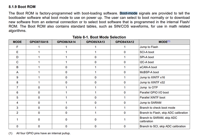
    Please take a look at the datasheet of the device, and look for boot-mode. Put the board in SCI mode which is same as 'Wait-in-reset' mode.

    https://www.ti.com/lit/gpn/tms320f28335

  • Hi Imran,

    Is this new controlCARD or it was working before and stopped working?  Looking at the error code, it looks like it was working before, and some code has been programmed in flash, but just wanted to confirm.

    Thanks & Regards,

    Santosh

  • Santosh Sir,

    I have purchased a new kit from digikey couple of months back so the board and card is new. I am eagerly wishing to be able to use it for the first time. I am still trying. There is noone around who has practical experience of using this device.

    I thank you for taking interest in solving my problem. 

    -Imran Siddiqui

  • Imran,

    If it is a new kit, I am assuming you have not changed the switch setting on the board.

    Can you try running GpioToggle example? Also, can you send the target configuration.

    Thanks & Regards,

    Santosh

  • Earlier I didn't knew about switches on the control card. But when I started to follow the threads here I  found them. I have put SW1 in the off position as I am using USB for communication though I have tried with ON position also and the result was same.

    I have configured target configuration as mentioned in document SPRUFR5H that came with the kit and elsewhere. I am unable to attach images as it is asking for url and there is no upload option. 

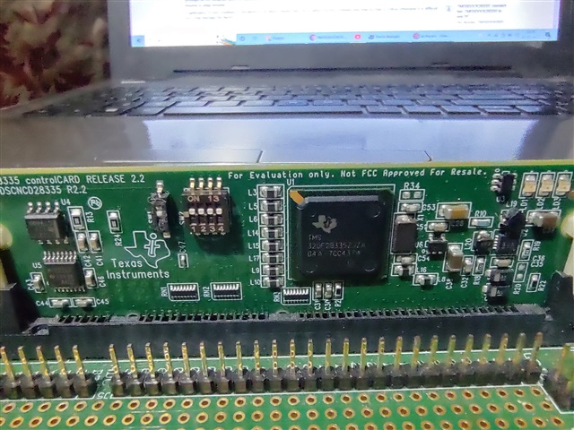
  • I just tested on my setup, it works fine. Here is my board with switch setting.

    You can just drag & drop in the reply edit box.

  • Drag and drop is opening a new tab in chrome browser while in edge it is not not allowed. However I am trying to put the device in the SCI A mode by driving pins GPIO 84, 85, 86, and  87. I have a confusion. Can I put the pins to high directly using the 5V supply on board or any resistor is required?

  • If this is new board, then it should be working. Did you check the pin setting is same I sent yesterday?

    You can drop the file in the edit box of reply. 

    Do you have any external emulator? xds100, xds510 etc

  • Yes the switch setting is same. No I don't have an external emulator. 

  • Can you check if it is enumerated in Windows Device manager?

    Are you still not able to attach the image?

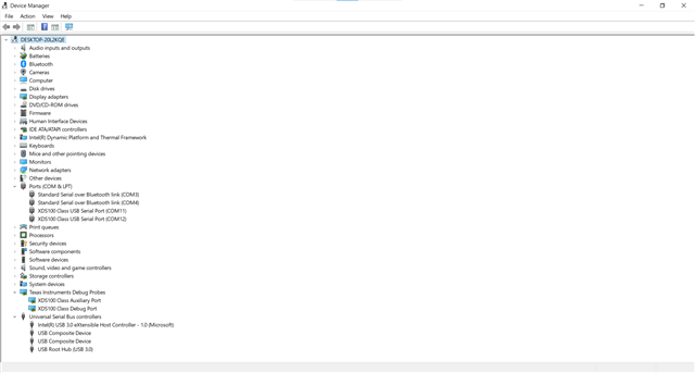
  • Yes it is displayed as xds100 class usb serial port in ports section and there also a separate section named Texas instruments debug probes in device manager.

    Image cannot be attached. A new window is getting opened with the image instead of getting added to the edit box. Also I have .ac.in email id provided by my university which is causing so much resistance in posting my reply. Anyways I'll manage it but image is not getting added through chrome or edge browser.

    If verification of lock condition of the device is an option please help me by telling me the complete way step by step to follow otherwise it is difficult and I may damage the device. 

  • Imran,

    Not sure why you cannot attach the picture. Everyone is able to attach it. May be you can save in a  doc file and attach. If it is enumerated properly, it should work fine. 

    Please take a look at this link. This has some e2e posts on how to resolve.

    https://software-dl.ti.com/ccs/esd/documents/ccs_debugging_jtag_connectivity_issues.html#c28x-device-locked

  • Hi Santosh,

        Good day!  Thanks for your patient support!

       I post on Imran's behalf because he encounter the difficulty to attach image. Please kindly help to check and suggest us, thank you so much!


    Best Regards
    Miao Bai

  • Let me take a look tomorrow and get back to you. I was OFF today

  • Hi, 

    We should see one LED lit on controlCard? Do you see that lit? Our guess is that the controlCard is not getting power. Can you check Pin1 and Pin51 on dock station (J1) has 3.3V?

    Also, can you check if J8 is populated or open? For JTAG to work, it should be open.

    Thanks, Santosh

  • That's what I mentioned in the question itself that the control card Led is not glowing. It gets on momentarily sometimes on power on.

    There is no pin on named 1 or 51 on board. But through schematic in pdf available in control suite I recognised that pin 1 corresponds to V33 pin on J3. It has a voltage of 1.2V. Apart from that,  5V and 3.3V are available adjacent to J1 where 5V and 3V3 is marked. J8 is open by default. 

  • Imran,

    When did you buy this controlCARD? 

  • May, 2022 from Digikey. 

  • I think there is some issue on board. Work with DigiKey to get RMA.

    Just curious why did you buy old device?

  • Actually I wanted to buy 28379d initially. But it is still out of stock. So now if I want to buy a new device both board and card need to be purchased or same board may work with 28379d card?

    Thanks for your support. 

  • What is the application? Do you need dual-core device?

    Did you look into launchpad? 

    Gen3 devices need new docking-station (base board)

  • Sorry for the late reply Sir. 

    I have to generate PWM switching signals for power electronic converters with frequency up to 10 or 20kHz. Switching signals from 6 pins may be needed simultaneously. 

    Thanks & Regards

  • Imran,

    Please pick launchpad or controlCARD of newer devices.

    https://www.ti.com/tool/TMDSCNCD280039C

    Thanks & Regards,

    Santosh