Part Number: LAUNCHXL-F28069M
Other Parts Discussed in Thread: DRV8312
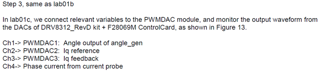
Hello everyone. I want to ask a few question, if i want to make a system identification for open loop system, and i need the data between speed (rpm) and voltage in three phase PMSM motor which is drive to run the motor, i've tried to follow instructions the InstaSPIN Lab 1b (Open loop V/F control) but why i don't have anything wave form in the datalog graph for angle, sampling current and volatge?
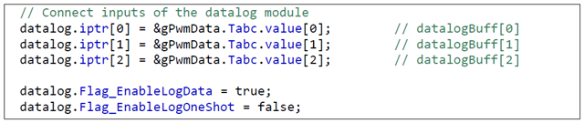
i don't really understand about the instruction to follow the PWMDAC and DATALOG, is this the program for the datalog?
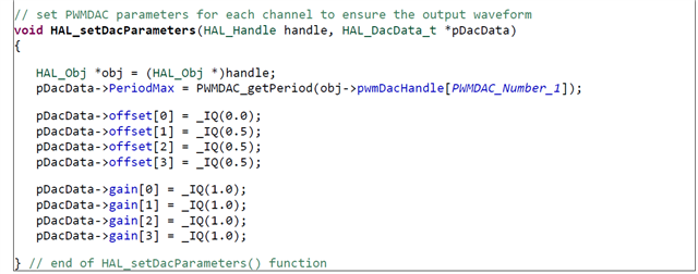
and for the PWMDAC, i've already write it the program like this, as the instrunction, but why in the graph i didn't see anything as the document?
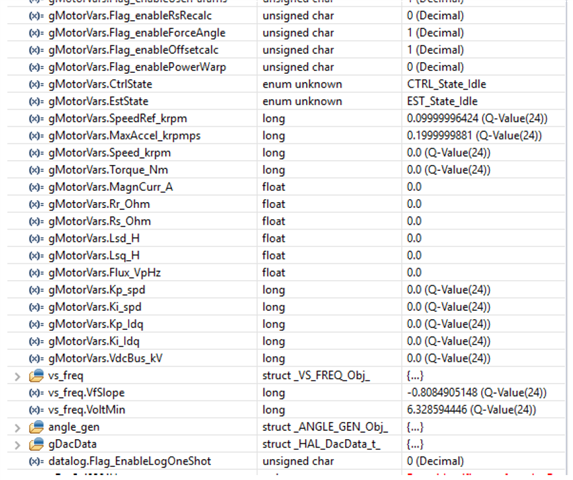
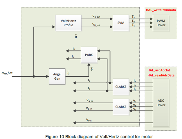
in the lab 01b, where i can see the voltage that used to run the motor in the watch window, as the block diagram bellow (V_alpha and V_betha)?
and for this step, is that means i have to trun off my power supply of my driver, here i have boostxl-8305evm?
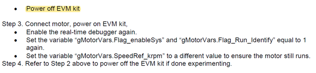
i've tried this 1-4 steps, and how do i know if i change the speed_ref it can be affect the regulated voltage and frequency of the motor? what should i look on the watch window? that indicate i've run this Lab is successfully.
thanks in advance.
Regards,
Fa