This thread has been locked.

If you have a related question, please click the "Ask a related question" button in the top right corner. The newly created question will be automatically linked to this question.

TMS320F28379D: HRPWM and Continuous Software Force on Outputs

Part Number: TMS320F28379D


Hi, could you please advise or share an example for how to force continuous outputs on PWMxA and PWMxB? I am working with a HRPWM and need to switch in between two modes 1) complementary output signals of HRPWM at PWMxA and PWMxB and 2) continuously hold  both PWM signals at low. 

I am using the code below and this requires a complete reprogramming of the DSP (running in debug mode) to enable the PWMs. I am looking for a software controlled solution that can switch in between two modes to make it practical especially when the build configuration is to be changed to Release.

        EALLOW;
        EPwm3Regs.HRCNFG.bit.SELOUTB  = HR_NORM_B;
        EDIS;

        EPwm3Regs.AQCSFRC.bit.CSFA =1;
        EPwm3Regs.AQCSFRC.bit.CSFB =1;

Code of HRPWM configuration: 

void HRPWM_Config(period)
{

    //
    // ePWM channel register configuration with HRPWM
    // ePWMxA / ePWMxB toggle low/high with MEP control on Rising edge
    //


    EALLOW;

      EPwm3Regs.HRCNFG.all = 0x0;
      EPwm3Regs.HRCNFG.bit.EDGMODE = HR_REP;  // MEP control on rising edge
      EPwm3Regs.HRCNFG.bit.CTLMODE = HR_CMP; // CMPAHR controls the MEP
      EPwm3Regs.HRCNFG.bit.HRLOAD  = HR_CTR_ZERO;  // Shadow load on CTR=Zero
      EPwm3Regs.HRCNFG.bit.EDGMODEB = HR_REP;  // MEP control on rising edge
      EPwm3Regs.HRCNFG.bit.CTLMODEB = HR_CMP;
      EPwm3Regs.HRCNFG.bit.HRLOADB  = HR_CTR_ZERO;
      EPwm3Regs.HRCNFG.bit.SELOUTB  = HR_INVERT_B; // 1: ePWMxB output is inverted version of ePWMxA signal.
      #if(AUTOCONVERT)
      EPwm3Regs.HRCNFG.bit.AUTOCONV = 1;      // Enable auto-conversion
                                               // logic
      #endif
      EPwm3Regs.HRPCTL.bit.HRPE = 0; // Turn off high-resolution period
                                      // control.

   EDIS;


   EPwm3Regs.TBCTL.bit.PRDLD = TB_SHADOW;  // set Shadow load
   EPwm3Regs.TBPRD = period-1;             // PWM frequency = 1 / period
   EPwm3Regs.CMPA.bit.CMPA = 0;   // set duty 0% initially
   EPwm3Regs.CMPA.bit.CMPAHR = (0 << 8);   // initialize HRPWM extension
   EPwm3Regs.CMPB.bit.CMPB = 0;   // set duty 0% initially
   EPwm3Regs.CMPB.all |= (0 << 8);         // initialize HRPWM extension
   EPwm3Regs.TBPHS.all = 0;
   EPwm3Regs.TBCTR = 0;

   EPwm3Regs.TBCTL.bit.CTRMODE = TB_COUNT_UP;
   EPwm3Regs.TBCTL.bit.PHSEN = TB_DISABLE;
   EPwm3Regs.TBCTL.bit.SYNCOSEL = TB_SYNC_DISABLE;
   EPwm3Regs.TBCTL.bit.HSPCLKDIV = TB_DIV1;
   EPwm3Regs.TBCTL.bit.CLKDIV = TB_DIV1;
   EPwm3Regs.TBCTL.bit.FREE_SOFT = 0x11;

   EPwm3Regs.CMPCTL.bit.LOADAMODE = CC_CTR_ZERO;  // LOAD CMPA on CTR = 0
   EPwm3Regs.CMPCTL.bit.LOADBMODE = CC_CTR_ZERO;
   EPwm3Regs.CMPCTL.bit.SHDWAMODE = CC_SHADOW;
   EPwm3Regs.CMPCTL.bit.SHDWBMODE = CC_SHADOW;


   EPwm3Regs.AQCTLA.bit.ZRO = AQ_CLEAR;      // PWM toggle high/low
   EPwm3Regs.AQCTLA.bit.CAU = AQ_SET;
   EPwm3Regs.AQCTLB.bit.ZRO = AQ_CLEAR;
   EPwm3Regs.AQCTLB.bit.CBU = AQ_SET;


        // Interrupt where we will change the Compare Values
            //
            EPwm3Regs.ETSEL.bit.INTSEL = ET_CTR_ZERO;     // Select INT on Zero event
            EPwm3Regs.ETSEL.bit.INTEN = 1;                // Enable INT
            EPwm3Regs.ETPS.bit.INTPRD = ET_3RD;           // Generate INT on 3rd event

}

  • Hi,

    I am looking for a software controlled solution that can switch in between two modes to make it practical especially when the build configuration is to be changed to Release.

    One solution that I can suggest is to try playing with the compare values (CMPA/B) to ensure desired duty ratio. On top of this, since you want both the PWMs to be low, you would need to change the configuration from complementary to independent.

    Other than that, you can try using the trip zone submodule. Based on the switching event from case 1 to case 2, you can set a GPIO pin to high based on which a trip can be generated and PWMs can be pulled low. When you again want to switch back to previous case of complementary PWM, you can clear the GPIO using which the trip will be cleared and PWMs can return to the normal complementary state.

    I feel the second approach should be an easy work around to your requirement. Can you give this a try?

    Thanks,

    Aditya

  • Hello Aditya, 

    I have already tried your first suggestion and this was also mentioned in my original request. With this portion of the code, I can force both PWMs to be low, but I don't know which command (reset etc.) to use for re-starting the PWM operation again.  

            EALLOW;
            EPwm3Regs.HRCNFG.bit.SELOUTB  = HR_NORM_B;
            EDIS;
    
            EPwm3Regs.AQCSFRC.bit.CSFA =1;
            EPwm3Regs.AQCSFRC.bit.CSFB =1;

  • You can clear the CSFA/B bits which will disable the software forcing.

    Did you try the second approach? That should be easier as well, similar to what you're doing using your approach.

    Aditya

  • Aditya, I have tried the second approach and both the PWMs do not go low with the following code. PWMA goes low and PWMB becomes high. Btw, I have a HRPWM running for EPWM3 (here PWMB is inverted of PWMA ) and not sure if interferes with the trip zone. 

    PWM initialization:

        EALLOW;
        EPwm3Regs.TZCTL.bit.TZA = 2;
        EPwm3Regs.TZCTL.bit.TZB = 2;
        EPwm3Regs.TZFRC.bit.OST=0; //Trip Zone Force Register
        EPwm3Regs.TZCLR.bit.OST=1; //Trip Zone Clear Register
        EDIS;
     

    And trip zone is software activated as follows:

      EALLOW;
      EPwm3Regs.TZFRC.bit.OST = 1; //Trip Zone Force Register
      EDIS;

  • PWMA goes low and PWMB becomes high

    You can configure the state of PWM that you desire by setting appropriate bits in the register.

    Regarding HRPWM operation, it won't affect the operation of the other 2 PWMs that you're using in normal mode.

    Thanks,

    Aditya

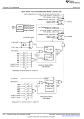
  • Do you agree with this observation? Complementary outputs of PWMA and PWMB, which although seem to be independently controlled by trip zone submodule (see figure below), cannot be forced to the same status set by the trip zone submodule. 

  • Trip signal is common but the actions that can be taken on the PWM is independent, i.e. based on one trip signal, you can choose whether you want to set the PWMs to high/low state independently.

  • There are 2 register bits separate to handle EPWMA and EPWMB available in the reg TBCTL. You can check out functionality of TBCTL[TZA] and TBCTL[TZB]