This thread has been locked.

If you have a related question, please click the "Ask a related question" button in the top right corner. The newly created question will be automatically linked to this question.

TMS320F280049C: CAN bit timing control registers for F280049C

Part Number: TMS320F280049C


Hi:

  is there documentation that is available that identifies how the CAN bit timing is identified in BTR0, BTR1 registers.  

Im doing the following:

CAN CLK = 100Mhz

CAN Baud rate: 1Mbaud
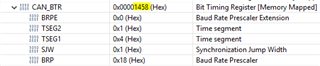
TSEG1: 3

TSEG2: 1
SJW: 1
BRP: 20

sample point of 80%.  

I just need to know how to convert this into the BTR0/1 registers.

Appreciate the help,

Abe

  • I just need to know how to convert this into the BTR0/1 registers.

    BTR0 is byte 0 (bits 0 to 7) of CAN_BTR.

    BTR1 is byte 1 (bits 8 to 15) of CAN_BTR.

    It's not clear from your question why you need  to know this/what you're trying to achieve. Are you wanting to configure a CAN USB PC interface to test your TI device CAN for example?

  • The TRM chapter explains the BTR registers. I have given 2 examples in www.ti.com/lit/SPRACE5. A very useful tool would be https://www.ti.com/lit/pdf/SPRAC35

  • HI i did use the examples in sprace5a to determine the bit timing as follows:

    Clock: 100Mhz

    BRP = 20

    TSEG1 = 3, TSEG2 = 1, SJW = 1

     100e6/(20*(3+1+1)) = 1000000 bps

    When i put this into the BTR0, i get (0101 0100)bin --> 0x54 hex

    When i put this into the BTR1, i get (0001 0011)bin --> 0x13 hex

    I needed to know this to configure a CAN USB PC interface for flashing the 280049C micro using a NI 8502.  However, it doesnt seem to respond to this.   I also have made the CAN bootlaoder match these settings and i have verified accurate CAN output when program is running at 1Mbaud.

    Appreciate any feedback.

    Abe

  • You need to reduce the values of BRP, TSEG1 & TSEG2 when writing to the CANBTR register. This is explained in in the TRM and also shown in SPRACE5. There is no BTR0, BTR1 etc. CAN_BTR is a 32-bit register. You need to write 0x00001253 in CANBTR. The tool I pointed you to does all this for you.

  • There is no BTR0, BTR1 etc. CAN_BTR is a 32-bit register.

    As Abe confirmed, he's trying to configure a PC CAN tool. This is usually done by inputting values for BTR0 and BR1 into some kind of HW config GUI. So he's asking what are the values of BTR0 and BTR1 for a given value of CAN_BTR in his micro.

    You're unnecessarily recalculating the values of BTR0/BTR1. Just copy them verbatim from the debugger. For example,
    I too use 1Mbps so I make the following simple configuration as follows:

        CAN_initModule( base );
    
        CAN_setBitRate( base, DEVICE_SYSCLK_FREQ, 1000000, 8);
    
        CAN_startModule( base );

    For my F2837xD, that results in the following CAN_BTR value.

    Therefore I would configure my PC CAN tool as BTR0 = 0x58 and BTR1 = 14. That's it.

    Having said that, in my experience, an incorrect sample point will not stop your CAN fundamentally communicating over short distances. If you are bench testing then just selecting a default 1000kbps setting should be more than adequate to get going. If you have no communication at all, then you (probably) have some other gross error beyond the values of BTR0 and BTR1.