This thread has been locked.

If you have a related question, please click the "Ask a related question" button in the top right corner. The newly created question will be automatically linked to this question.

TMDSCNCD28388D: SFRA result is not correct

Part Number: TMDSCNCD28388D
Other Parts Discussed in Thread: TMDXIDDK379D, C2000WARE, , SFRA, INA240

Hi,

I am using TI example firmware located in:

\ti\c2000\C2000Ware_MotorControl_SDK_4_00_00_00\solutions\tmdxiddk379d\f2838x\

on TI control card, TMDSCNCD28388D, 

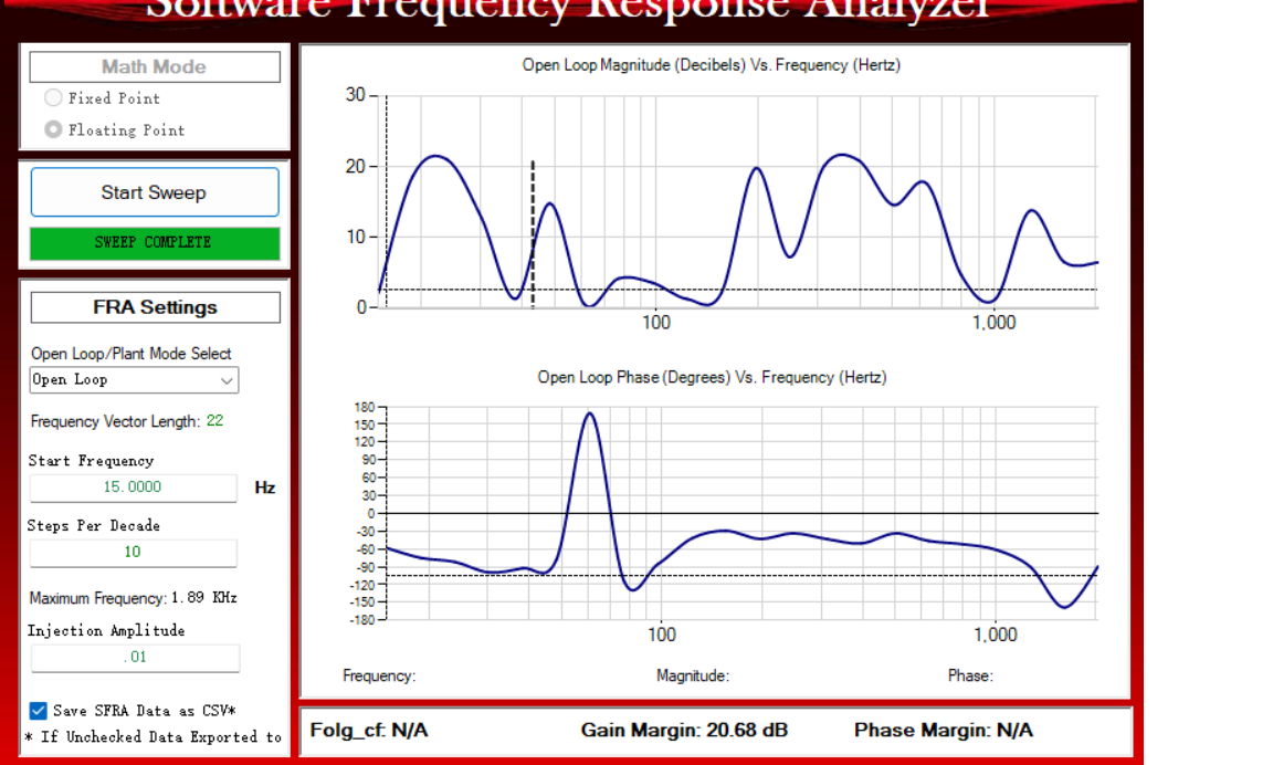
to run SFRA program, which is level 6 setting in the example firwmare.

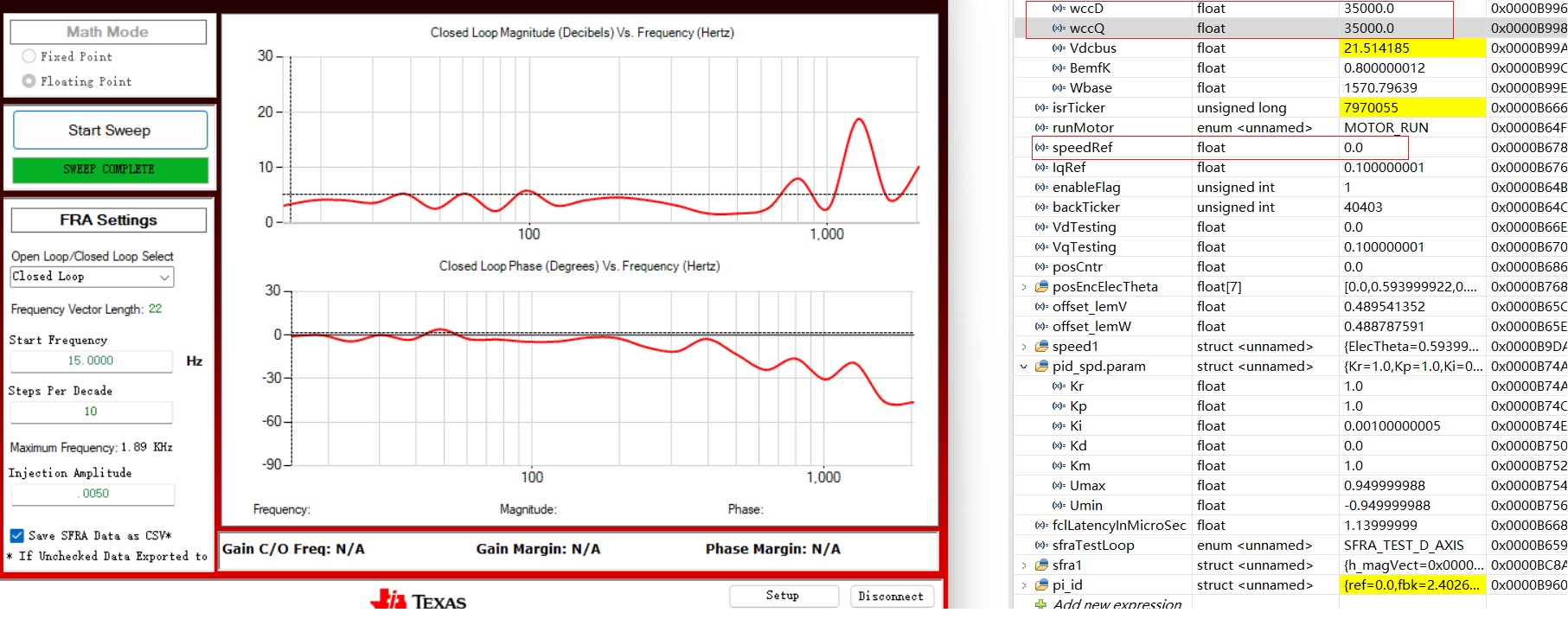
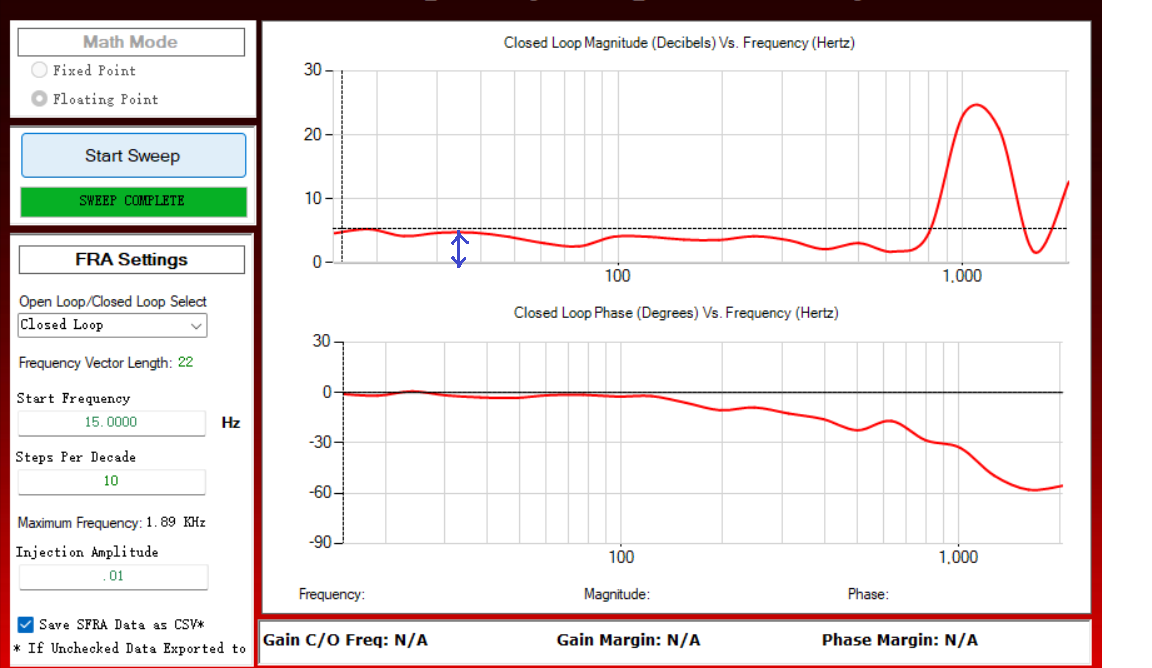
The motor is running normally, but the SFRA result seems to be not correct. the screen shot is below.

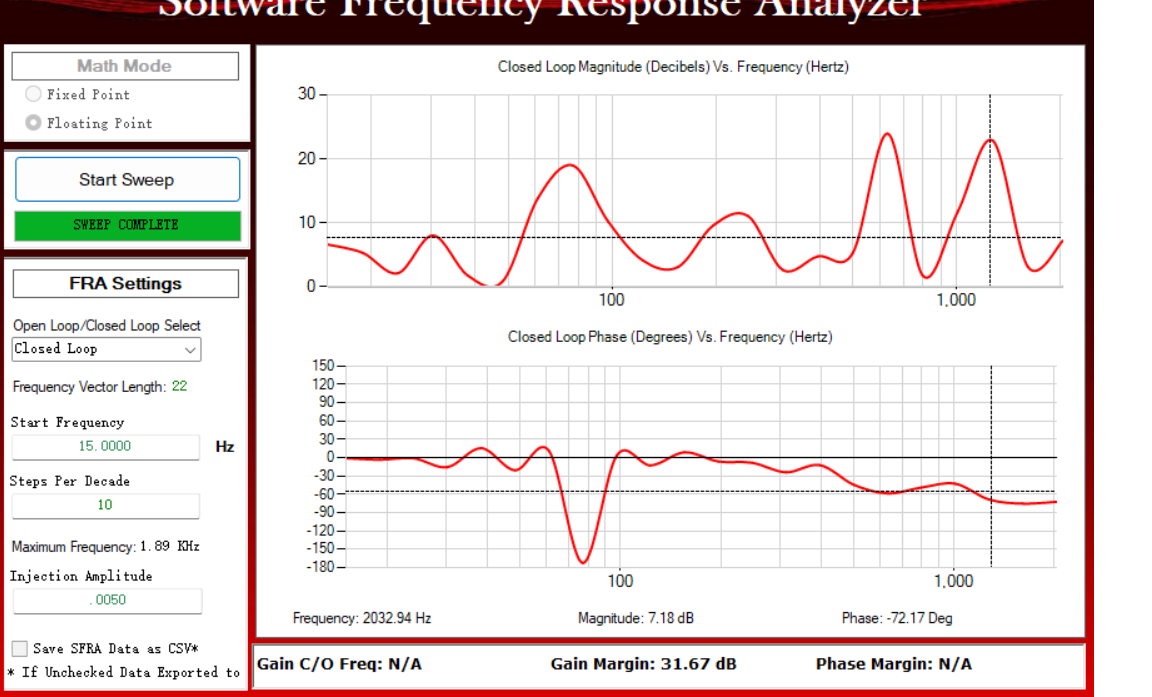
I try to tune the injection amplitude to a higher value, but the result is not improved.

What's wrong with it ? How can I get the correct results ?

  • Can you try switching to open-loop mode instead and then try tuning the injection amplitude?

    Whitney

  • Hi Whitney,

    I have also tried open-loop mode, but the result is not improved. By tuning the injection amplitude, it seems no much improvement. The open-loop result is as below,

    Whatever using SFRA_GUI or SFRA_GUI_MC, the result are similar.

  • I have stoped here for days, no any progress. Any one give an indication?

  • Are you using SFRA for current loop or speed loop?

    The waveform could be not as the current loop since the control bandwidth is too low for speed loop. You can try to tune the PI control parameters if using SFRA for current loop.

  • Hi, Yanming,

    I use the default d-axis current loop with default current bandwidth settings to test SFRA. 

    If I increase current bandwidth settings, the similar oscillation wave can be seen. So I guess there must be a mistake existed somewhere. 

  • What's the PWM/control frequency you used? SFRA toll is better to use a higher control frequency to sample the enough data. You may try to tune the Kp & Ki to achieve a better performance on gain and phase margin.

  • Hi Yanming,

    I use the default settings in the example firmware. such as, 10kHz pwm frequency.  PI control. Single sampling or double sampling. LEM phase current sampling mode settings (but in my hardware, I use two INA240 chip to sample the phase current). The most of them are default settings.

    In SFRA test, I have not tune the current loop Kp or Ki seperately.  I just adjust the bandwidth setting of current loop, which are FCL_params.wccD, FCL_params.wccQ. But the result is not improved. 

    Next, I will adjust Kp & Ki seperately to have a try. Any result, I will let you know. 

  • OK. The SFRA tool is better for digital power control with a higher control bandwidth, the same requirement for motor control.

  • I have tried to tune current PI Kp, Ki, but it is diffcult to get a satisfied result on SFRA. 

    I found a better result which is set zero speed reference. The motor shaft is zero speed. the SFRA phase curve is better then that the motor shaft rotates. But the amplitude seems to be not improved a lot. the result below is current loop ID SFRA test, when the FCL_params.wccD, FCL_params.wccQ are both set to 35000.  The sampling mode is double sampling mode.

    Although the waves are better than the previous, but it is still hard to judge the true bandwidth of current loop of ID from the plot.

    I believe there are something may be wrong or wrong settings or wrong design. 

    Can you help me to analyze the deep reason?

  • You can try to increase the injection amplitude and keep tuning the control bandwidth as well. Meanwhile, make sure the motor electrical parameters are set correctly.

  • OK, I will try to tune as you said. But in the previous test, the control bandwidth setting is as large as 35000, I almost hear some noises. Anyway, I will try tune them again including injection amplitude and verify the motor parameter settings.

    The SFRA settings such as, start frequency, steps per decades,can be set in GUI. Can I adjust them?

    In addition, how to extend the display ranges of x-axis in Bode plot, currently it only displays 1000Hz and above 1000Hz, the frequency value labels are not displayed. As for current loop bandwidth, defnitely it will be higher than 1000Hz, but on the current Bode plot figure, the values over 1000Hz can not be numerically displayed. How can I extend the x-axis range and display it normally?

  • Hi,

    Yanming is out of office today. Please expect response by Monday. 

    Thanks & Regards,

    Santosh

  • You can take a look at the user's guide below.

    C2000Tm Software Frequency Response Analyzer (SFRA) Library and Compensation Designer User's Guide

    The display range is fixed that could be enough for most of the applications. 

  • Hi Yanming,

    Thanks for you doc linking address.

    Actually, I have the doc and I have read it.

    Since I use the TI example firmware for SFRA test, so the settings related to SFRA are already available in the firmware. 

    I have tunned the current loop bandwidth. The better result is achieved as below, but it is still not ideal.

    The settings is as below: 
    FCL_params.wccD = 20000;

    FCL_params.wccQ=20000;

    The SFRA test is ID axis;

    The motor parameters is:

    Rs=0.055ohm; Ls=0.000095H;

    Flux=0.0384 elec-V/Hz;

    poles=10;

    motor rated voltage =24V; 

    I am sure set the correct motor parameters.

    The test is performed under speed_ref=0rpm; And only in 0 speed, the above curve is obtained and seems to be close to normal. If there is some speed in non-zero, the plot is very strange and oscillate much more across the frequence axis.

    As we can see from the amplitude bode plot, it seems a constant gain, like 5dB. as we know, the ideal should be kept at zero dB at low frequences. so what does it mean for the 5dB ?

    And I found that adjusting injection amplitude does not have much influence on the final plot.

    I think the above result is very close to the ideal case, but I cannot find further measures to adjust it. 

    Any further comment on it are appreciated.

  • No more further comments for you, just as mentioned above to tune the control bandwidth or gains of the controller. More description about SFRA you may refer to the guide mentioned above.