Other Parts Discussed in Thread: TMDSCNCD28388D
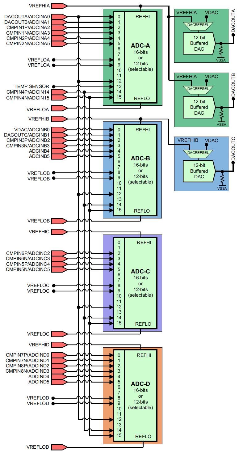
In datasheet and TRM from TMS320F28388D data sheet, product information and support | TI.com, I can find these two pictures to show ADC block diagram. My understanding is this DSP has 24 ADC input pins but I can only use 16 of them.
1. Does it mean I can pick them randomly if I am using single end signal? what if I configure 17 pins?
2. If I am using differential input, according to TMDSCNCD28388D design file, it looks like if I pick A2 as P, N has to be A3, is it correct?
3. If I pick ADCINB2 as input, how can I know which pin it is among ADCIN0-15?
4. According to the picture below, the four ADC units are not the same, correct? A, B and D have 8 ADC inputs but C only has 6.
Pictures are in page 131 in datasheet and Page 2520 in TRM.