Part Number: TMS320F28388D
Other Parts Discussed in Thread: DP83822I, C2000WARE, TMDSCNCD28388D, TMDSHSECDOCK
I am developing an Ethernet using TMS320F28388D.
The PHY being spec'd is dp83822i.
(Configuration is described below)
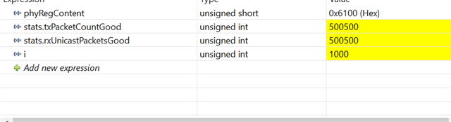
I am using the C2000ware driver to make the initial Ethernet settings. When I set "10Mbps", both transmit and receive succeed, but when I set "100Mbps", there are many errors when receiving.
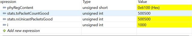
Looking at the Statistic, the cause of the errors seems to be "rxCRCErrorPackets". 10Mbps does not cause this problem.
The PHY BMCR is selected correctly, so I do not think there is a problem on the PHY side. auto-nego is checked with OFF, but the same behavior is observed with ON.
The test environment consists of two boards with the above environment and a program in which only the MAC address has been changed.
TMS320F28388D <--(RMII)--> dp83822i <--(Full/100M)--> dp83822i <--(RMII)--> TMS320F28388D
Is there anything I have forgotten to set when using "100Mbps"?
Ethernet_InitInterfaceConfig initInterfaceConfig;
Ethernet_InitConfig *pInitCfg;
initInterfaceConfig.ssbase = EMAC_SS_BASE;
initInterfaceConfig.enet_base = EMAC_BASE;
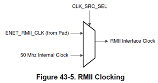
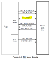
initInterfaceConfig.phyMode = ETHERNET_SS_PHY_INTF_SEL_RMII;
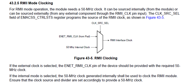
initInterfaceConfig.clockSel = ETHERNET_SS_CLK_SRC_EXTERNAL; // PHY : RMII Master mode. PHY output 50Mhz clock. EMAC input.
initInterfaceConfig.ptrPlatformInterruptDisable = &Platform_disableInterrupt;
initInterfaceConfig.ptrPlatformInterruptEnable = &Platform_enableInterrupt;
initInterfaceConfig.ptrPlatformPeripheralEnable = &Platform_enablePeripheral;
initInterfaceConfig.ptrPlatformPeripheralReset = &Platform_resetPeripheral;
initInterfaceConfig.peripheralNum = SYSCTL_PERIPH_CLK_ENET;
initInterfaceConfig.interruptNum[0] = INT_EMAC;
initInterfaceConfig.interruptNum[1] = INT_EMAC_TX0;
initInterfaceConfig.interruptNum[2] = INT_EMAC_TX1;
initInterfaceConfig.interruptNum[3] = INT_EMAC_RX0;
initInterfaceConfig.interruptNum[4] = INT_EMAC_RX1;
pInitCfg = Ethernet_initInterface(initInterfaceConfig);
Ethernet_getInitConfig(pInitCfg);
pInitCfg->pktMTU = 1536;
pInitCfg->numChannels = 2;
for ( i = 0U; i < pInitCfg->numChannels; i++ ) {
pInitCfg->chInfo[ETHERNET_CH_DIR_TX][i].numBD = 1;
pInitCfg->chInfo[ETHERNET_CH_DIR_TX][i].chNum = i;
pInitCfg->chInfo[ETHERNET_CH_DIR_RX][i].numBD = 8;
pInitCfg->chInfo[ETHERNET_CH_DIR_RX][i].dmaBufferSize = 384; // dmaBuffSize <<= 2 ; // RX Only
pInitCfg->chInfo[ETHERNET_CH_DIR_RX][i].chNum = i;
}
pInitCfg->emacSSConfig.phyIntfSel = ETHERNET_SS_CTRLSTS_PHY_INTF_SEL_RMII;
pInitCfg->emacSSConfig.clkSrcSel = ETHERNET_SS_CTRLSTS_CLK_SRC_SEL_EXTERNAL;
pInitCfg->emacSSConfig.LoopBackModeClkSel = ETHERNET_SS_CTRLSTS_LMCLKSEL_NORMAL;
pInitCfg->emacSSConfig.flowControlEn = ETHERNET_SS_CTRLSTS_FLOW_CTRL_EN_DISABLED;
pInitCfg->loopbackMode = ETHERNET_MAC_CONFIGURATION_LM_LOOPBACK_DISABLED;
pInitCfg->maxPacketLengthRxBuffer = 1536;
pInitCfg->dmaMode.TxRxArbitration = ETHERNET_DMA_OPERATION_MODE_DA_ROUND_ROBIN; // DA //
pInitCfg->dmaMode.TransmitPriority = 0; // TXPR // Priority Rx
pInitCfg->dmaMode.PriorityRatio = ETHERNET_DMA_OPERATION_MODE_PR_TX4_RX1; // PR // Rx4:Tx1
pInitCfg->linkMode = ETHERNET_MAC_CONFIGURATION_DM_FULL_DUPLEX;
pInitCfg->pfcbGetPacket = &func_CB_pfcbGetPacket; // self
pInitCfg->pfcbRxPacket = &func_CB_pfcbRxPacket; // self
pInitCfg->pfcbFreePacket = &func_CB_pfcbFreePacket;// self
/* Since the buffer for descriptors is managed and operated by the user,
pInitCfg->rxBuffer is not necessary. */
Ethernet_getHandle((Ethernet_Handle)1, pInitCfg, &etHandel);
Ethernet_clearMACConfiguration( EMAC_BASE, 0x2 ); // TX Disable
Ethernet_clearMACConfiguration( EMAC_BASE, 0x1 ); // RX Disable
(void)Interrupt_enableInProcessor();
Interrupt_registerHandler(INT_EMAC_TX0, Ethernet_transmitISR);
Interrupt_registerHandler(INT_EMAC_TX1, Ethernet_transmitISR);
Interrupt_registerHandler(INT_EMAC_RX0, Ethernet_receiveISR);
Interrupt_registerHandler(INT_EMAC_RX1, Ethernet_receiveISR);
Interrupt_enable(INT_EMAC_TX0);
Interrupt_enable(INT_EMAC_TX1);
Interrupt_enable(INT_EMAC_RX0);
Interrupt_enable(INT_EMAC_RX1);
/* MAC Address Set */
uint32_t mac[2] = {0};
device->emacMACaddrCfg.channelNum = 0; // instanseNUM 0 = ETHERNET_O_MAC_ADDRESS0, 1 = ETHERNET_O_MAC_ADDRESS1, 2... 0-7
mac[0] = ((uint32_t)m_MAC.addr[4] << 8 | m_MAC.addr[5]);
mac[1] = ((uint32_t)m_MAC.aaddr[0] << 24 | m_MAC.addr[1] << 16 |
m_MAC.aaddr[2] << 8 | m_MAC.addr[3]);
Ethernet_setMACAddr( EMAC_BASE, // Base Address
0, // InstansNum 0-7
mac[0], // MAC Address HIGH
mac[1], // MAC Address LOW
ETHERNET_CHANNEL_0); // CHANNEL0 or CHANNEL1
/* Change Speed, Duplex */
uint16_t mdio_reg = PHY_MdioRegRead( 0x0010 );
/* linkSpeed ( MAC_Configuration Register "FES" ) */
if ( (mdio_reg & 0x2) != 0 ) Ethernet_clearMACConfiguration( EMAC_BASE, ((uint32_t)1 << 14) ); // EMAC 100Mbps
else Ethernet_setMACConfiguration( EMAC_BASE, ((uint32_t)1 << 14) ); // EMAC 10Mbps
/* linkMode ( MAC_Configuration Register "DM" ) */
if ( (mdio_reg & 0x4) != 0 ) Ethernet_setMACConfiguration( EMAC_BASE, ((uint32_t)1 << 13) ); // EMAC Full Duplex
else Ethernet_clearMACConfiguration( EMAC_BASE, ((uint32_t)1 << 13) ); // EMAC Half Duplex
Ethernet_setMACConfiguration( EMAC_BASE, 0x2 ); // TX Enable
Ethernet_setMACConfiguration( EMAC_BASE, 0x1 ); // RX Enable