This thread has been locked.

If you have a related question, please click the "Ask a related question" button in the top right corner. The newly created question will be automatically linked to this question.

TMS320F280049-Q1: Analog Corner Pins

Part Number: TMS320F280049-Q1

Hi team,

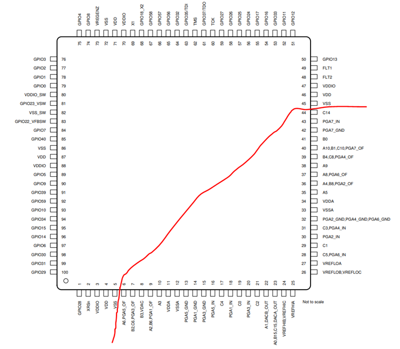
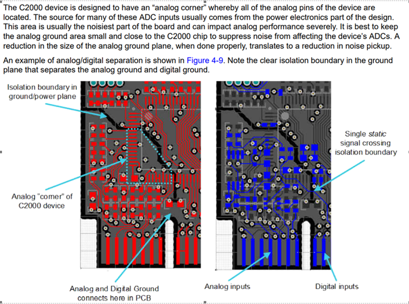
For F280049PZQ (100-pin LQFP package), what is the "analog corner" referring to? Could you please clarify if the below "analog corner" applies to F280049PZQ (100-pin LQFP package) and if so, what are the pins customer need to apply the isolation boundary to separate the "corner"? Based on Table 6-1, analog pins are located from pin 6 to pin 44, so the "analog corner" should be from pin 6 to pin 44? 

Below from "Hardware Design Guide for F2800x C2000Tm Real-Time MCU Series" - 

https://www.ti.com/lit/an/spracz9/spracz9.pdf
  • Hi Pengyu,

    You are exactly correct in your interpretation of the analog corner. The analog corner of the device simply refers to the corner which contains all of the analog signals (ADCIN, PGA, DACs, VREFs, VDDA, VSSA, etc.). If possible in the layout, it is recommended to isolate these areas of the chip, with separate ground planes for analog and for digital. The line that you've drawn in your figure is right. 

    Regards,

    Peter