Hello All
I am new to digital PID control implementation, though not to embedded development.
I am trying to implement fixed point (double loop of volt and current) PID control of half bridge sine inverter using piccolo 28035.
For this implementation, I take two adc signals, 1. Output voltage and 2. Inductor current.
In the outer loop, the (sine ref - output volt) is computed to get error and in the inner loop, voltage pi output is used as reference and inductor current is subtracted.
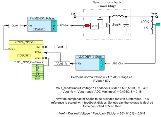
But there is a step of normalization in which these adc values are typically multiplied by different constants (the process of normalization) and sine ref is also built to suit the same. The details of this step is missing even in TI's UPS ref design SPRA589a.pdf
Can some digital PI expert explain the process of normalization and show an implementation with an example? Or pointers to the resource will be OK. This will be very useful for beginners like me.
Thanks.
Sayee