This thread has been locked.

If you have a related question, please click the "Ask a related question" button in the top right corner. The newly created question will be automatically linked to this question.

TMS320F28069: Example code for Comparator block and Slope compensation implemetation

Part Number: TMS320F28069
Other Parts Discussed in Thread: TIDM-02000

Hi all

I want to know is there any resource i can refer to get help for implement the peak current mode control. 
There are only two recourses i found and it was not readable at all. One of them was written i  assembly for no reason. 
Other one is also written with lines which use direct access to the registers, also not readable. Whole register written at once and cannot understand how to configure slope compensation and comparator blocks 
 One of them is the TIDM-02000. 
See the following code snippet used for comparator config. 

    ASSERT(CMPSS_isBaseValid(base));

    //
    // Write the high comparator configuration to the appropriate register.
    //
    EALLOW;

    HWREGH(base + CMPSS_O_COMPCTL) =
        (HWREGH(base + CMPSS_O_COMPCTL) & ~CMPSS_HICMP_CTL_M) | config;

    EDIS;
}

This is not readable at all. Why they used this raw data access when there is a perfect registry structure defined by TI, for each registry access.

Can you please suggest how i can find a readable code for this comparator block and slope compensation hardware.

This development example didn't used a single registry structure.
What is the meaning of developing a code no one can read, especially when it comes to reference designs. 
Why TI engineers no longer use the convenient Registry peripheral structures like in the past. 

Regards
Damith

  • Hi Damith,

    Understood it is kind of different from the original bit field based solution. We added the comment in both solution file and driverlib file to help the readability. 

    The code you mentioned is actually inside the driverlib library (cmpss.h) which is how TI is using now for all new reference design(including TIDM-02000). Below doc contains the introduction of driverlib vs bit field(assuming you are requesting for). Hope that helps answer part of your question.

    https://software-dl.ti.com/C2000/docs/software_guide/_static/pdf/C2000_Software_Guide.pdf

    We still have needed s/w support for bit field code if you want to use it.

    Pls let us know if you have any further comments or questions.

    Regards,

    Chen

  • Dear Chen

    Thank you very much for the references you mentioned. That helps. 
    I'm sorry but i cannot understand how it is easier to write the whole registry and get in trouble when we want to find the specific bit description from the technical guide. Because in bit field style, we can easily refer the technical guide and debug what we missed in configuring the hardware properly. But in this so-called higher-level mode, it's a headache to find which bit is wrong because all the configurations for that specific registry, are enclosed into a single byte. 
    What is the point of having technical guide in bit field style while codes are in Arduino style.
    Sure, this will ease the programming for entry level like lighting an LED in Arduino, but that's it. 
    When it comes to advanced prototyping, this will create lots of unnecessary troubles going between technical Gulde and the code. 
    For example, if i want to create complex PWM waveforms for a Power converter, it is very easy in the bit field mode because i can manipulate the various bits of ePWM module easily to get my PWM. But this "higher level" makes it very hard to understand what each bit does. This bitField style was the main thing that made TI refence designs easy to read and gave fast learning curve for new Devices but seems like it is no longer the case. 
    Reference designs became just plug and play projects. Not easy to adapt the solutions. 

    Regards
    Damith

  • Hi Damith,

    i cannot understand how it is easier to write the whole registry and get in trouble when we want to find the specific bit description from the technical guide. Because in bit field style, we can easily refer the technical guide and debug what we missed in configuring the hardware properly. But in this so-called higher-level mode, it's a headache to find which bit is wrong because all the configurations for that specific registry, are enclosed into a single byte.

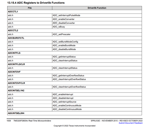
    I got your point. I We actually have considered this point and add the look up table in the TRM. For example below, you can easily find the function related to the register you want. And you don't have to consider which exactly the bit sometimes since the function provides the options for the parameters(easy to read) that are used. Do understand this is different from how you do it in the past. 

    www.ti.com/.../sprui33e.pdf

    page 1658: 12.15.4

    Do understand this is not that straightforward for people who have strong familiarity on each bit of the register since they can directly change the bit they want. 

    Regards,

    Chen

  • Hi chen

    Thank you for the explanation.
    Can you please tell me what information the following table gives us other than these functions are in the adc.h file.?
    How this table made it easier to find which functions set which bits. As i can see, this guide also added bit field description. 

    Thank you