This thread has been locked.

If you have a related question, please click the "Ask a related question" button in the top right corner. The newly created question will be automatically linked to this question.

TMS320F280045: Code does not start without debug active

Part Number: TMS320F280045
Other Parts Discussed in Thread: TMS320F280049C, TM4C1292NCPDT,

Dear Sirs

As with the related post, "application does not start without debugger active", my code won't run upon power reset.  Please see configuration below.  


MEMORY
{
PAGE 0 :
   /* BEGIN is used for the "boot to Flash" bootloader mode   */

   BEGIN           	: origin = 0x080000, length = 0x000002
   RAMM0           	: origin = 0x0000F6, length = 0x00030A

   RAMLS0          	: origin = 0x008000, length = 0x000800
   RAMLS1          	: origin = 0x008800, length = 0x000800
   RAMLS2      		: origin = 0x009000, length = 0x000800
   RAMLS3      		: origin = 0x009800, length = 0x000800
   RAMLS4      		: origin = 0x00A000, length = 0x000800
   RESET           	: origin = 0x3FFFC0, length = 0x000002

   /* Flash sectors */
   /* BANK 0 */
   FLASH_BANK0_SEC0  : origin = 0x080002, length = 0x000FFE	/* on-chip Flash */
   FLASH_BANK0_SEC1  : origin = 0x081000, length = 0x001000	/* on-chip Flash */
   FLASH_BANK0_SEC2  : origin = 0x082000, length = 0x001000	/* on-chip Flash */
   FLASH_BANK0_SEC3  : origin = 0x083000, length = 0x001000	/* on-chip Flash */
   FLASH_BANK0_SEC4  : origin = 0x084000, length = 0x001000	/* on-chip Flash */
   FLASH_BANK0_SEC5  : origin = 0x085000, length = 0x001000	/* on-chip Flash */
   FLASH_BANK0_SEC6  : origin = 0x086000, length = 0x001000	/* on-chip Flash */
   FLASH_BANK0_SEC7  : origin = 0x087000, length = 0x001000	/* on-chip Flash */
   FLASH_BANK0_SEC8  : origin = 0x088000, length = 0x001000	/* on-chip Flash */
   FLASH_BANK0_SEC9  : origin = 0x089000, length = 0x001000	/* on-chip Flash */
   FLASH_BANK0_SEC10 : origin = 0x08A000, length = 0x001000	/* on-chip Flash */
   FLASH_BANK0_SEC11 : origin = 0x08B000, length = 0x001000	/* on-chip Flash */
   FLASH_BANK0_SEC12 : origin = 0x08C000, length = 0x001000	/* on-chip Flash */
   FLASH_BANK0_SEC13 : origin = 0x08D000, length = 0x001000	/* on-chip Flash */
   FLASH_BANK0_SEC14 : origin = 0x08E000, length = 0x001000	/* on-chip Flash */
   FLASH_BANK0_SEC15 : origin = 0x08F000, length = 0x001000	/* on-chip Flash */

   /* BANK 1 */
   FLASH_BANK1_SEC0  : origin = 0x090000, length = 0x001000	/* on-chip Flash */
   FLASH_BANK1_SEC1  : origin = 0x091000, length = 0x001000	/* on-chip Flash */
   FLASH_BANK1_SEC2  : origin = 0x092000, length = 0x001000	/* on-chip Flash */
   FLASH_BANK1_SEC3  : origin = 0x093000, length = 0x001000	/* on-chip Flash */
   FLASH_BANK1_SEC4  : origin = 0x094000, length = 0x001000	/* on-chip Flash */
   FLASH_BANK1_SEC5  : origin = 0x095000, length = 0x001000	/* on-chip Flash */
   FLASH_BANK1_SEC6  : origin = 0x096000, length = 0x001000	/* on-chip Flash */
   FLASH_BANK1_SEC7  : origin = 0x097000, length = 0x001000	/* on-chip Flash */
   FLASH_BANK1_SEC8  : origin = 0x098000, length = 0x001000	/* on-chip Flash */
   FLASH_BANK1_SEC9  : origin = 0x099000, length = 0x001000	/* on-chip Flash */
   FLASH_BANK1_SEC10 : origin = 0x09A000, length = 0x001000	/* on-chip Flash */
   FLASH_BANK1_SEC11 : origin = 0x09B000, length = 0x001000	/* on-chip Flash */
   FLASH_BANK1_SEC12 : origin = 0x09C000, length = 0x001000	/* on-chip Flash */
   FLASH_BANK1_SEC13 : origin = 0x09D000, length = 0x001000	/* on-chip Flash */
   FLASH_BANK1_SEC14 : origin = 0x09E000, length = 0x001000	/* on-chip Flash */
   FLASH_BANK1_SEC15 : origin = 0x09F000, length = 0x000FF0	/* on-chip Flash */

//   FLASH_BANK1_SEC15_RSVD : origin = 0x09FFF0, length = 0x000010  /* Reserve and do not use for code as per the errata advisory "Memory: Prefetching Beyond Valid Memory" */

PAGE 1 :

   BOOT_RSVD       : origin = 0x000002, length = 0x0000F1     /* Part of M0, BOOT rom will use this for stack */
   RAMM1           : origin = 0x000400, length = 0x0003F8     /* on-chip RAM block M1 */
//   RAMM1_RSVD      : origin = 0x0007F8, length = 0x000008     /* Reserve and do not use for code as per the errata advisory "Memory: Prefetching Beyond Valid Memory" */

   RAMLS5      : origin = 0x00A800, length = 0x000800
   RAMLS6      : origin = 0x00B000, length = 0x000800
   RAMLS7      : origin = 0x00B800, length = 0x000800

   RAMGS0      : origin = 0x00C000, length = 0x002000
   RAMGS1      : origin = 0x00E000, length = 0x002000
   RAMGS2      : origin = 0x010000, length = 0x002000
   RAMGS3      : origin = 0x012000, length = 0x001FF8
//   RAMGS3_RSVD : origin = 0x013FF8, length = 0x000008     /* Reserve and do not use for code as per the errata advisory "Memory: Prefetching Beyond Valid Memory" */
}


SECTIONS
{
   codestart        : > BEGIN,     PAGE = 0, ALIGN(4)
   .text            : >> FLASH_BANK0_SEC2 | FLASH_BANK0_SEC3 | FLASH_BANK0_SEC5,   PAGE = 0, ALIGN(4)
   .cinit           : > FLASH_BANK0_SEC1,     PAGE = 0, ALIGN(4)
   .switch          : > FLASH_BANK0_SEC1,     PAGE = 0, ALIGN(4)
   .reset           : > RESET,     PAGE = 0, TYPE = DSECT /* not used, */

   .stack           : > RAMM1,     PAGE = 1

#if defined(__TI_EABI__)
   .init_array      : > FLASH_BANK0_SEC1,       PAGE = 0,       ALIGN(4)
   .bss             : > RAMLS5,       PAGE = 1
   .bss:output      : > RAMLS3,       PAGE = 0
   .bss:cio         : > RAMLS0,       PAGE = 0
   .data            : > RAMLS5,       PAGE = 1
   .sysmem          : > RAMLS5,       PAGE = 1
   /* Initalized sections go in Flash */
   .const           : > FLASH_BANK0_SEC4,       PAGE = 0,       ALIGN(4)
#else
   .pinit           : > FLASH_BANK0_SEC1,       PAGE = 0,       ALIGN(4)
   .ebss            : > RAMLS5,       PAGE = 1
   .esysmem         : > RAMLS5,       PAGE = 1
   .cio             : > RAMLS0,       PAGE = 0
   .econst          : > FLASH_BANK0_SEC4,    PAGE = 0, ALIGN(4)
#endif

   ramgs0           : > RAMGS0,    PAGE = 1
   ramgs1           : > RAMGS1,    PAGE = 1

 
#if defined(__TI_EABI__) 
   .TI.ramfunc      : LOAD = FLASH_BANK0_SEC1,
                      RUN = RAMLS0,
                      LOAD_START(RamfuncsLoadStart),
                      LOAD_SIZE(RamfuncsLoadSize),
                      LOAD_END(RamfuncsLoadEnd),
                      RUN_START(RamfuncsRunStart),
                      RUN_SIZE(RamfuncsRunSize),
                      RUN_END(RamfuncsRunEnd),
                      PAGE = 0, ALIGN(4)
#else					  
   .TI.ramfunc      : LOAD = FLASH_BANK0_SEC1,
                      RUN = RAMLS0,
                      LOAD_START(_RamfuncsLoadStart),
                      LOAD_SIZE(_RamfuncsLoadSize),
                      LOAD_END(_RamfuncsLoadEnd),
                      RUN_START(_RamfuncsRunStart),
                      RUN_SIZE(_RamfuncsRunSize),
                      RUN_END(_RamfuncsRunEnd),
                      PAGE = 0, ALIGN(4)
#endif

}

/*
//===========================================================================
// End of file.
//===========================================================================
*/
               

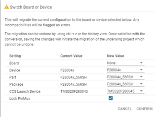
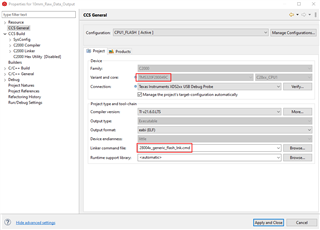
I'm not running a bootloader.  I noticed the BEGIN: origin starts at 0x080000.  I would have thought it should start at 0x000000.  I've tried the 280045_FLASH_lnk.cmd file but have linker errors saying that the code won't fit in the memory.  I've noticed that the Variant and core: setting is TMS320F280049C.  The drop down is grayed out so I can't change it.  As you can see, the uC has been switched to TMC320F280045_56RSH.  Will this have any effect on the memory mapping?  Please help.  Thank you.

  • Hi,

    how do you verify that your code is not running?

    Did you try to attach debugger to running device (i.e. without programming flash, no reset but only halt) and see what is strange?

    You can see where in the code processor is halted (PC register, disssembly view), if it entered and left startup initialization code. 

    Regards,
    Piotr Romaniuk

  • Thanks Piotr for responding.

    Dennis: Lets know who you are checking the function.

    Thanks & Regards,

    Santosh

  • Dear Mr. Romanluk

    how do you verify that your code is not running?

    I'm sorry for the late reply.  I've been out of the office for three days.  Let me run through my setup.  I have two boards that communicate with each other.  One is a SPI slave and the other is the master.  The slave is the data acquisition board, and the master board collects the data and sends it out to a laptop over a RS485 communication line.  The procedure is as follows.  The slave sends a data ready pulse to the master, this triggers an interrupt in the master.  Then the master starts the SPI data transfer.  once the data transfer is complete, the master sends the data to the laptop where it's stored in a file.  The slave board uses a TMS320F280045 uC and the master board uses a TM4C1292NCPDT uC.  I know that the master board is booting and running on power up because it sends out a preamble to the laptop on power up.  I observe this with a terminal application.  I'm using the Spectrum Digital XDS200 JTAG emulator for both boards.  I do not connect both emulators at the same time.  With the emulator connected to the slave, I download the code to and start the debug session.  The slave starts the data acquisition, the slave and master communicate as they should, and the master sends out the data to the laptop.  When I return to the code editor mode, the two boards continue to operate as they should.  I've disconnected the emulator from the slave while the two boards are running, and they continue to operate.  However, if I now cycle power, the slave board doesn't boot.  I see the master preamble but no data.  Leaving the emulator connected has no effect.  

    Did you try to attach debugger to running device (i.e. without programming flash, no reset but only halt) and see what is strange?

    You can see where in the code processor is halted (PC register, disssembly view), if it entered and left startup initialization code. 

    I'm not sure what you want me to do here.  What is the procedure to get to the state where I can look at the halt point and the registers?  Are you saying that I download the code, start the debug session and then power cycle the board while in the debug session?  

    Seeing the BEGIN address in the linker command file at 0x00800000 leads me to believe that this is the problem.  Again, I would have thought it should start at 0x00000000.  I've tried the 280045_FLASH_lnk.cmd file, which has the BEGIN address at 0x00000000, but have linker errors saying that the code won't fit in the memory.  Your thoughts on this.  Thank you.

  • Dear Mr. McGlumphy,

    Let me just start from last part of your response:

    Seeing the BEGIN address in the linker command file at 0x00800000 leads me to believe that this is the problem.  Again, I would have thought it should start at 0x00000000.  I've tried the 280045_FLASH_lnk.cmd file, which has the BEGIN address at 0x00000000, but have linker errors saying that the code won't fit in the memory.

    As you see Flash memory starts from 0x80000, so this is correct in linker file.

    Please verify that in hardware you have selected flash boot - you need to have at power on: GPIO24=1, GPIO32=1 (see Table 8-13 p.198 https://www.ti.com/lit/gpn/tms320f280045). 

    I had similar problem when my start address was different than start of the flash - please check it if you really build the program for 0x80000. It worked fine with emulator but not started when it was stand alone.

    You can also verify by emulator what is at 0x80000. There should be branch instruction to your startup code.

    Kind regards,

    Piotr Romaniuk

  • I'm not sure what you want me to do here.  What is the procedure to get to the state where I can look at the halt point and the registers?  Are you saying that I download the code, start the debug session and then power cycle the board while in the debug session?  

    If you have some unusual behaviour that is dependent on emulator (here: if is connected and starts the program) you need to not disturb the state of processor. I think you can try something like this:

    1. program your software into the flash memory,
    2. disconnect emulator (hardware connection),
    3. cycle the power
    4. here you observe the sympthoms of the problem
    5. connect emulator to the board,
    6. now you need to connect debuger (software) but not reset the cpu, nor program it. It should suspend the cpu 
    7. you will be able to observe where the execution stuck (memory type, the address), what is the state of other registers

    Firstly, I advise to check if your setup is correct by disconnecting (debugging perspective of CCS, icon "Connect target" ) the debugger (but not closing it) when your software works fine and connecting again. You will be able to verify if you can have [7]. No reset or restart should be. 

    Now let me give you some directions how to connect debugger in the attach mode:

    Method 1. - use custom debug configuration setup where you only load the symbols but not program.
    All steps in manual method 2 should be available in GUI of CCS. Unfortunatelly I had a problems with it.

    Method 2. - configure step by step:

    1. open debugger perspective (do not start debuger yet),
    2. open view | target configuration 
    3. find your current configuration and select "Launch Selected Configuration" in right mouse button menu,
      1. if you succeed you will see the core/cores of your CPU in Debug View
    4. select your CPU in Debug View
    5. click on Connect Target Icon 

    If your CPU will reset you probably need to modify GEL file that is in your target configuration. I just removed resets, memory clean at start up etc.

    Kind regards,

    Piotr Romaniuk

  • Dear Mr. Romanluk

    My design has GPIO24 and GPIO32 unconnected.  I assume this is the problem.  Is there any way that I can initialize these GPIOs with weak pullup to get the flash boot mode configuration?  I don't use these GPIOs on this board.  But if I would need these GPIOs, how would I go about using them for flash boot mode and GPIOs within the application?  

  • Dear Mr. McGlumphy,

    Is there any way that I can initialize these GPIOs with weak pullup to get the flash boot mode configuration? 

    I am affraid there is not. This is very early stage of boot sequence (if you wander please see booting sequence description in technical reference).

    You need electrical connection for pulling them up to power supply, e.g. by two resistors 10k. Remember that you need to provide these pull-ups only when the power supply is being enabled (only at this moment). You don't need to solder anything. Please try to verify if it is the reason. 

    But if I would need these GPIOs, how would I go about using them for flash boot mode and GPIOs within the application?  

    I am not sure if you can get rid of this boot selection function on gpio at all. There is a lot of gpio pins.
    It is possible (I know it from similar c2000 chip; you need to confirm this in he documentation for your chip) to move them to another gpio. It involves programming OTP (ONE! Time Programming) memory - Z1_BOOTCTRL. It is irreverible, so don't do this unless you really need this and you know what you are doing. 

    Kind regards,

    Piotr Romaniuk

  • I applied the 10K pullup resistor to GPIO pins 24 and 32.  It was a real pain but the uC now boots from flash.  Thanks for the help.

  • Dear Mr. McGlumphy,

    I am glad the problem is solved.

    Can you also mark my message where I suggested to pull up the boot inputs as the solution?
    I hope I will earn some points for that.

    Regards,

    Piotr Romaniuk

  • Dear Mr. Romanluk

    Please verify that in hardware you have selected flash boot - you need to have at power on: GPIO24=1, GPIO32=1 (see Table 8-13 p.198 https://www.ti.com/lit/gpn/tms320f280045).
    My design has GPIO24 and GPIO32 unconnected.  I assume this is the problem.  Is there any way that I can initialize these GPIOs with weak pullup to get the flash boot mode configuration?
    I am affraid there is not. This is very early stage of boot sequence (if you wander please see booting sequence description in technical reference).

    Thank you for pointing this out.  The text didn't say these GPIO pins were absolutely required for boot configuration.  I thought there may be another way.