This thread has been locked.

If you have a related question, please click the "Ask a related question" button in the top right corner. The newly created question will be automatically linked to this question.

Using generated PWM signal as a variable

Other Parts Discussed in Thread: TMS320F28335

I am using DSP F28335 to control a converter.

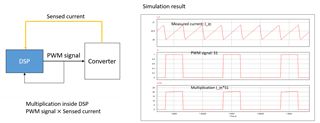
Currently, I have to use the generated PWM signal from ePWM module as a variable. I mean I need to get the multiplication between generated PWM signal and a sensed current signal.

Is there any method to get the PWM signal?

Thanks!

  • I am using TMS320F28335 to control the converter.

    Currently, I create PWM signal using ePWM module and set GPIO as an output.

    I want to use that PWM signal as a variable in the control part. So, I think about reading the status of GPIO output pin using GPADAT register.

    GpioCtrlRegs.GPAPUD.bit.GPIO2 = 0; /* Enable pull-up on GPIO2 (EPWM2A) */
    GpioCtrlRegs.GPAMUX1.bit.GPIO2 = 1; /* Configure GPIO2 as EPWM2A */

    I set a variable named "test1" to store the data of GPIO2

    test1 = GpioDataRegs.GPADAT.bit.GPIO2;

    However, when I watch the Expression window, the variable "test1" always equals 0.

    Can anyone help me this issue?

  • Hello Hoang,

    Is this the total configuration you have set? It seems you are missing the direction configuration (GpioCtrlRegs.GPADIR.bit.GPIO2). The default direction is input, which may be why you're seeing only 0. Also, to verify that data is being output you should scope the pin rather than reading the variable within the code, as this will show if it's actually being routed out of the device.

    Best regards,

    Omer Amir

  • Hi Hoang,

    I mean I need to get the multiplication between generated PWM signal and a sensed current signal.

    Can you please describe in further detail what you mean by this? What exactly are you multiplying? A diagram may help if possible. 

    Best Regards,

    Marlyn

  • First, thank you so much for replying, Omer Amir.

    As you said, it's correct. I do not have the direction configuration (using GPADIR register).

    My initial purpose is to use the generated PWM signal as a variable because I need to make a multiplication between a sensed signal and PWM signal. Do you have any advice?

    Thank you in advance!

  • Hi Marlyn,
    First, thank you much for replying.

    I add a picture corresponding to my issue. In the simulation, I can easily make a multiplication between measured current and PWM signal. Now I want to implement it in the experiment using DSP. 

    Thank you in advance!

  • I also add the line GpioCtrlRegs.GPADIR.bit.GPIO2 = 1; to my code for direction configuration. The value of "test1" still be 0.

  • Hello Hoang,

    My initial purpose is to use the generated PWM signal as a variable because I need to make a multiplication between a sensed signal and PWM signal.

    By this, do you mean you want to output a signal that's a product of the sensed signal and the PWM?

    The value of "test1" still be 0.

    Have you tried testing other pins on the board? Do they have the same issue?

    Best regards,

    Omer Amir

  • Hi Hoang,

    For the EPWM state, you could just read the value of the GPIO (through software) that you are using for the epwm output, this will tell you the current state of the epwm, high (1) or low (0).

    Best Regards,

    Marlyn

  • HI Marlyn,

    I tried reading the status of GPIO output pin using GPADAT register.

    GpioCtrlRegs.GPAPUD.bit.GPIO2 = 0; /* Enable pull-up on GPIO2 (EPWM2A) */
    GpioCtrlRegs.GPAMUX1.bit.GPIO2 = 1; /* Configure GPIO2 as EPWM2A */

    I set a variable named "test1" to store the data of GPIO2

    test1 = GpioDataRegs.GPADAT.bit.GPIO2;

    However, when I watch the Expression window, the variable "test1" always equals 0.

    Thank you in advance!

  • 1. Correct, I want to output a signal that's a product of the sensed signal and the PWM to use in my control algorithm.

    2. I changed the code a little bit. It seems working now. As I see in the Expression window, the variable "test1" varies between 0 and 1 now,

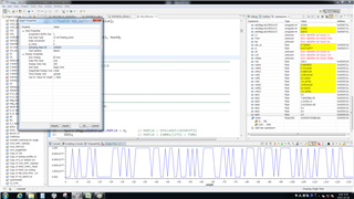
    I want to check the variable "test1" is correct or not, so I used graph tool to draw the variable "test1". However, the waveform of "test1" seems be not correct, as you can see in the attached picture.


    Thank you in advance!

  • Hi Marlyn, 

     I changed the code a little bit. It seems working now. As I see in the Expression window, the variable "test1" varies between 0 and 1 now,

    I want to check the variable "test1" is correct or not, so I used graph tool to draw the variable "test1". However, the waveform of "test1" seems to be not correct, as you can see in the attached picture.

    Thank you in advance!

  • Hello Hoang,

    I may have to ask another expert to weigh in on this, since it seems that you are trying to essentially create a DAC, rather than just using a GPIO pin. Give me some time to contact another expert.

    Best regards,

    Omer Amir

  • Hi Hoang,

    How often are you updating the value of test1? This may be due to how frequent you check the status of the GPIO.

    Best Regards,

    Marlyn

  • Hi Hoang,

    Can you show me how you are using the PWM and sensed signal to create the output signal? Are you using the sensed signal to change the duty of the PWM? I want to clarify what it is you're doing and what you are trying to achieve with your algorithm.

    Best regards,

    Omer Amir

  • Hi Amir,

    I have an algorithm, that needs to use the multiplication between PWM and sensed signals. I just simply use that multiplication for some calculation equations.

    I do not use the sensed signal to change the duty of the PWM. 

    Thank you in advance!!!

  • Currently, may ADCCLK is 6.25Mhz, with ACQ is 1.

  • Hello Hoang,

    The algorithm makes sense, but how are you trying to output this signal on a digital pin? From what I've read in the manual for this device, there is no DAC to convert the digital value of a multiplication product into a voltage output. The GPIO can only be changed to a 1 or 0 using the registers. How are you attempting get a variable voltage without using a DAC?

    Best regards,

    Omer Amir

  • Hi Hoang,

    How fast is your EPWM frequency? If you slow down the frequency do you see the GPIO reading more closely reflect the correct output?

    Best Regards,
    Marlyn

  • Hi Amir,

    Actually, I do not need to output that signal on a digital pin. I just want to use it inside the DSP for my algorithm.

    Normally, to get a signal from a digital pin, I use an external DAC circuit.

    Thanks.

  • Hello Hoang,

    Okay, I think I understand your issue much better now. When you use the graphing tool in CCS, can you graph the memory location of the input signal? We can try to debug why your resulting multiplication isn't as expected. You should store the incoming signal at some memory address and then graph those values to see it in total. Before it seemed like you were just graphing the GPIO pin's value, which only has a 0 or 1 as far as I know.

    Best regards,

    Omer Amir

  • Hello Amir,

    The waveform in this picture is just GPIO pin's value, not the multiplication. Currently, the GPIO's pin value is not as expected.
    My PWM frequency is 5kHz, ADCCLK is 6.25Mhz, with ACQ is 0.
    The current issue is just related to GPIO pin's value to get PWM signal.

    Thank you so much!

  • Hi Marlyn,

    The ePWM frequency was 5kHz.
    I tried reducing ePWM frequency but the GPIO pin's value is not as expected.

    Thank you in advance!

  • Hello Hoang,

    If this graph is reading the incoming signal, I'm not sure why you're graphing the GPIO pin. This will always be digital (1 or 0, nothing in between), so it won't show the I_in signal the way you described above. To view an input signal, you should have an array of some set size where the ADC results of the input signal are stored, and then graph that in CCS. That way the input can be converted to something that CCS will view. Please graph the ADC results of the input signal and I will do my best to help debug any issue that you're seeing from that.

    Best regards,

    Omer Amir

  • Hoang, 

    Have you already scoped out the EPWM signal to make sure the epwm output is correct? 

    Best Regards,

    Marlyn

  • Hi Marlyn,

    I already scoped out the epwm signal with different frequencies and duty cycles. They're all correct.

    Thanks!

  • Hi Amir, 

    I need to explain the situation again. 

    What I want now is the correct pwm signal to make the multiplication between sensed current and that pwm signal.

    I tried reading the status of GPIO pin's value using GPADAT register as followed

    GpioCtrlRegs.GPAPUD.bit.GPIO2 = 0; /* Enable pull-up on GPIO2 (EPWM2A) */
    GpioCtrlRegs.GPAMUX1.bit.GPIO2 = 1; /* Configure GPIO2 as EPWM2A */
    GpioCtrlRegs.GPADIR.bit.GPIO2 = 1

    test1 = GpioDataRegs.GPADAT.bit.GPIO2;

    The previous graph depicted the variable "test1", I mean the GPIO pin's value. However, as can be seen in that graph, the waveform was not as expected, it did not follow the PWM signal that was scoped out. Currently, I am having an issue reading the GPIO pin's value.

    I really appreciate your help.

  • Hello Hoang,

    I see that you made a duplicate thread on this question, I'm merging it so we can keep the information within one thread.

    Best regards,

    Omer Amir

  • Hello Hoang,

    After trying to read the GPIO pin for the ePWM on our side as well, we have come up with an alternative solution. By using the TBCTR register within the ePWM peripheral, you can read this count and use a conditional to check what values it's between to determine when it's 0 or 1. This way, you do not have to read the pin (which may not be accurate because it cannot be continuously read without delay). Instead, you can use a conditional to check the current count and determine if this count is within the high pulse or low pulse. You can determine this based on your TBPRD value and your duty.

    Let me know if you have further questions about this.

    Best regards,

    Omer Amir

  • Hello Amir,

    First, thank you so much for helping me.

    I tried using a condition between TBCTR, TBPRD, and duty cycle. In this case TBPRD = 37500, duty cycle = 50%, PWM frequency = 2kHz.

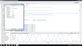
    However, the variable "test1", shown in the Expression window, changes slowly. It's not as expected. I mean the graph of variable "test1", shown in the below picture, is not as expected.


    I attach my code below. Please help me to check this.
    I really appreciate your help!

    //============================================================================================
    // 선행처리 지시
    //--------------------------------------------------------------------------------------------
    #include "DSP28x_Project.h"						// Device Headerfile and Examples Include File
    #include "math.h"
    #include "stdio.h"
    #include "stdlib.h"
    #include "float.h"
    
    #define TBCLK			150E6
    #define PWM_SAMPLE      5E3///100us
    #define PWM_CARRIER      2E3
    //============================================================================================
    ////CALCULATION TIME is 20.8us as for 2016/12/18
    //============================================================================================
    //	함수 선언
    //--------------------------------------------------------------------------------------------
    void InitEPwmModules(void);
    //interrupt void adc_isr(void);					// ADC 인터럽트 함수 선언
    interrupt void cpu_timer0_isr(void);
    //double lowpass(double input);
    //============================================================================================
    //============================================================================================
    // 시스템에서 사용할 전역 변수 선언
    //--------------------------------------------------------------------------------------------
    
    float64 tim, tfault, Tsp,theta, time;
    
    float32 iup, ilow, vc1, vc2, vc3, vc4, vc5, vc6;
    float32 vc1_1, vc2_1, vc3_1, vc4_1, vc5_1, vc6_1;
    float32 vref;
    float32 k1, k2, k3, k4, k5, Vdc, f1;
    
    float32 iz, v_avg, v_avg_error, iz_est, iz_error;
    float32 v_avg_error_sum, iz_error_sum;
    float32 V_avg_ref;
    float32 sign_up, sign_low;
    float32 vc1_bal, vc2_bal, vc3_bal, vc4_bal, vc5_bal, vc6_bal;
    float32 ref1, ref2, ref3, ref4, ref5, ref6;
    float32 vmod, Test;
    float32 a1, pi, m;
    
    // current and voltage sensors----------------//
    Uint32 x0,x1,x2,x3,x4,x5,x6,x7,x8,x9;
    float32 X11,X12,X13,X14,X15,X16,X17,X18,X19;
    float32 at1;
    
    float32 Ithres, Vthres;
    Uint16 cont, fault_flag, detect, flag, flag2;
    Uint16 t1,t2,t3,t4,t5,t6,t7,t8;
    Uint16 s1a,s2a,s3a,s4a,s5a,s6a;
    Uint16 s1a_1,s2a_1,s3a_1,s4a_1,s5a_1,s6a_1;
    
    float32 LOW_LIM, UP_LIM;
    float32 idc, adc_vdc;
    float32 test1, test2, test3, test4;
    float32 counter1, counter2;
    //============================================================================================
    void main(void)
    {
    //============================================================================================
    // Step 1. 전역 인터럽트 비활성화
    //--------------------------------------------------------------------------------------------
    	DINT;
    //============================================================================================
    //============================================================================================
    // Step 2. 시스템 컨트롤 초기화:
    //--------------------------------------------------------------------------------------------
    	InitSysCtrl();
    	EALLOW;
    	SysCtrlRegs.HISPCP.bit.HSPCLK = 1;  	// HSPCLK = SYSCLKOUT/(HISPCP*2)
    	EDIS;									// HSPCLK = 150MHz/(0*2) = 150MHz
    
    	EALLOW;
    
    	GpioCtrlRegs.GPAMUX1.bit.GPIO0 = 1; //EPWM1A out
    	GpioCtrlRegs.GPAMUX1.bit.GPIO1 = 1; //EPWM1B out
    	GpioCtrlRegs.GPAMUX1.bit.GPIO2 = 1; //EPWM2A out
    	GpioCtrlRegs.GPAMUX1.bit.GPIO3 = 1; //EPWM2B out
    	GpioCtrlRegs.GPAMUX1.bit.GPIO4 = 1; //EPWM3A out
    	GpioCtrlRegs.GPAMUX1.bit.GPIO5 = 1; //EPWM3B out
    	GpioCtrlRegs.GPAMUX1.bit.GPIO6 = 1; //EPWM4A out
    	GpioCtrlRegs.GPAMUX1.bit.GPIO7 = 1; //EPWM4B out
    	GpioCtrlRegs.GPAMUX1.bit.GPIO8 = 1; //EPWM5A out
    	GpioCtrlRegs.GPAMUX1.bit.GPIO9 = 1; //EPWM5B out
    	GpioCtrlRegs.GPAMUX1.bit.GPIO10 = 1; //EPWM6A out
    	GpioCtrlRegs.GPAMUX1.bit.GPIO11 = 1; //EPWM6B out
    
    	GpioCtrlRegs.GPADIR.bit.GPIO0 = 1;
    	GpioCtrlRegs.GPADIR.bit.GPIO1 = 1;
    	GpioCtrlRegs.GPADIR.bit.GPIO2 = 1;
    	GpioCtrlRegs.GPADIR.bit.GPIO3 = 1;
    	GpioCtrlRegs.GPADIR.bit.GPIO4 = 1;
    	GpioCtrlRegs.GPADIR.bit.GPIO5 = 1;
    	GpioCtrlRegs.GPADIR.bit.GPIO6 = 1;
    	GpioCtrlRegs.GPADIR.bit.GPIO7 = 1;
    	GpioCtrlRegs.GPADIR.bit.GPIO8 = 1;
    	GpioCtrlRegs.GPADIR.bit.GPIO9 = 1;
    	GpioCtrlRegs.GPADIR.bit.GPIO10 = 1;
    	GpioCtrlRegs.GPADIR.bit.GPIO11 = 1;


    	//GpioCtrlRegs.GPADIR.bit.GPIO0 = 1;/////setting outputs
    	//GpioCtrlRegs.GPADIR.bit.GPIO1 = 1;
    
    
    /*
    	GpioCtrlRegs.GPAMUX1.bit.GPIO10 = 0;
    	GpioCtrlRegs.GPADIR.bit.GPIO10 = 1;
    	GpioCtrlRegs.GPAMUX1.bit.GPIO11 = 0;
    	GpioCtrlRegs.GPADIR.bit.GPIO11 = 1;
    */
    
    
    	EDIS;
    //============================================================================================
    
    //============================================================================================
    // Step 3. 인터럽트 초기화:
    //--------------------------------------------------------------------------------------------
    	InitPieCtrl();
    	IER = 0x0000;
    	IFR = 0x0000;
    	InitPieVectTable();
    	// Vector Remapping
    	EALLOW;
    	//PieVectTable.ADCINT = &adc_isr;
    	PieVectTable.TINT0= &cpu_timer0_isr;
    	EDIS;
    //============================================================================================
    //============================================================================================
    // Step 4. ADC 초기화
    //--------------------------------------------------------------------------------------------
    	InitAdc();
    	// ADC 설정
    	AdcRegs.ADCTRL3.bit.ADCCLKPS = 0;	   		// ADCCLK = {HSPCLK/[(ADCCLKPS*2)*(CPS+1)]}/(CPS+1)=75MHZ
    	AdcRegs.ADCTRL1.bit.CPS = 1;				// ADCCLK = {150MHz/[(3*2)*(1+1)]}/(1+1) = 37.5MHz
    	AdcRegs.ADCTRL1.bit.ACQ_PS = 0;				// 샘플/홀드 사이클 = ACQ_PS + 1 = 1 (ADCCLK기준)=0.026us
    
    	AdcRegs.ADCTRL1.bit.SEQ_CASC = 1;			// 시퀀스 모드 설정: 직렬 시퀀스 모드 (0:병렬 모드, 1:직렬 모드)
    	AdcRegs.ADCTRL3.bit.SMODE_SEL = 0;			// 순차 샘플링 모드
    
    	AdcRegs.ADCMAXCONV.all = 8;  				// ADC 채널수 설정: 8개(=MAX_CONV+1)채널을 ADC
    
    	AdcRegs.ADCCHSELSEQ1.bit.CONV00 = 0; 		// ADC 순서 설정: 1번째로 ADCINA0 채널을 ADC
    	AdcRegs.ADCCHSELSEQ1.bit.CONV01 = 3; 		// ADC 순서 설정: 2번째로 ADCINA3 채널을 ADC
    	AdcRegs.ADCCHSELSEQ1.bit.CONV02 = 4; 		// ADC 순서 설정: 3번째로 ADCINA4 채널을 ADC
    	AdcRegs.ADCCHSELSEQ1.bit.CONV03 = 8; 		// ADC 순서 설정: 4번째로 ADCINB0 채널을 ADC
    	AdcRegs.ADCCHSELSEQ2.bit.CONV04 = 11;		// ADC 순서 설정: 5번째로 ADCINB3 채널을 ADC
    	AdcRegs.ADCCHSELSEQ2.bit.CONV05 = 12;		// ADC 순서 설정: 6번째로 ADCINB4 채널을 ADC
    	AdcRegs.ADCCHSELSEQ2.bit.CONV06 = 15;		// ADC 순서 설정: 7번째로 ADCINB7 채널을 ADC
    	AdcRegs.ADCCHSELSEQ2.bit.CONV07 = 7;
    
    
    //	AdcRegs.ADCTRL2.bit.EXT_SOC_SEQ1 = 1;		// ADC 시퀀스 완료시 인터럽트 발생 설정
    	//AdcRegs.ADCTRL2.bit.INT_ENA_SEQ1 = 1;		// ADC 시퀀스 완료시 인터럽트 발생 설정
    	//AdcRegs.ADCTRL2.bit.INT_ENA_SEQ2 = 1;		// ADC 시퀀스 완료시 인터럽트 발생 설정
    
    	// PIE의 ADC 인터럽트 활성화
    	//PieCtrlRegs.PIEIER1.bit.INTx6 = 1;			//Adc Interrupt Enabled
    
    //============================================================================================
    
    //============================================================================================
    // Step 5. PWM 초기화
    //--------------------------------------------------------------------------------------------
    	InitEPwmModules();
    //============================================================================================
    // Step 5.1 Timer0 초기화
    //--------------------------------------------------------------------------------------------.
    
    //============================================================================================
    // Step 6. Initialize Application Variables
    //--------------------------------------------------------------------------------------------
        at1=(1/21840.0);
    
    	test1=0;
    
    cont=0;
    //============================================================================================
    
    CpuTimer0Regs.PRD.all  = (150000000./PWM_SAMPLE)-1;
    //CpuTimer0Regs.PRD.all  = 7500-1;
    CpuTimer0Regs.TCR.bit.TSS=1;////// The timer is not operating (TIMEr STOP)
    CpuTimer0Regs.TCR.bit.TRB=1;//// Loads PRD to TIM to start the count-down of the Timer counter
    
    CpuTimer0Regs.TPR.bit.TDDR = 0;//// Set the timer pre-scalator to 0 (TimerCLock=SYSCLOCK)
    
    CpuTimer0Regs.TCR.bit.TIE = 1;//////ENABLE TIMER INTERRUPT
    CpuTimer0Regs.TCR.bit.TSS = 0;//////START OPERATION OF TIMER
    CpuTimer0Regs.TCR.bit.FREE=1;///////FREE RUN ENABLE (NO stops by debugger breaking points)


    IER |= M_INT1; 								// CPU 인터럽트(INT1)  활성화
    IER &= 0x0001;
    PieCtrlRegs.PIEIER1.bit.INTx7=1;			//CpuTimer0 Interrupt Enabled
    PieCtrlRegs.PIEACK.all=1;


    //============================================================================================
    // 전역 인터럽트 활성화 , 리얼타임 디버깅 인터럽트 활성화:
    //--------------------------------------------------------------------------------------------
    	EINT;   // Enable Global interrupt INTM
    	ERTM;   // Enable Global realtime interrupt DBGM
    //============================================================================================
    
    //============================================================================================
    // IDLE loop. Just sit and loop forever :
    //--------------------------------------------------------------------------------------------
    	for(;;)
    	{
    
    
       	}
    //============================================================================================
    
    }
    //============================================================================================
    //	메인 함수 - 끝
    //============================================================================================
    
    //============================================================================================
    //	인터럽트 서비스 루틴 정의
    //--------------------------------------------------------------------------------------------
    
    interrupt void cpu_timer0_isr(void)
    {
    
    	PieCtrlRegs.PIEACK.bit.ACK1=1;
    
    	AdcRegs.ADCTRL2.bit.RST_SEQ1 = 1;
    	AdcRegs.ADCTRL2.bit.SOC_SEQ1=1;
    
    
    		///Regenerate epwm1 signal///
    			counter1 = EPwm1Regs.TBPRD;
    			counter2 = EPwm2Regs.TBCTR;
    			
    			if (counter2 > 0.5*counter1)
    			{
    				test1 = 0;
    			}
    			else
    			{
    				test1 = 1;
    			}
    
    			EPwm1Regs.CMPA.half.CMPA = EPwm1Regs.TBPRD * 0.5 ;
    			EPwm2Regs.CMPA.half.CMPA = EPwm2Regs.TBPRD * 0.5 ;
    
    tim=tim+Tsp;
    
    			return;
    
    }


    void InitEPwmModules(void)
    {
    		// Setup Period (Carrier Frequency)
    		EPwm2Regs.TBPRD = (TBCLK/PWM_CARRIER)/2.;	// Set Timer Period,
    		EPwm2Regs.TBCTR = 0;						// Clear Counter
    
    		// Set Compare Value
    		EPwm2Regs.CMPA.half.CMPA =0;	// Set Compare A Value to 0%
    
    		// Setup Phase
    		EPwm2Regs.TBPHS.half.TBPHS = EPwm2Regs.TBPRD;		// Phase is 180
    		EPwm2Regs.TBCTL.bit.PHSEN = 1;		// Disable phase loading
    		EPwm2Regs.TBCTL.bit.PHSDIR = 0;
    		EPwm2Regs.TBCTL.bit.PRDLD = 0;		// Period Reg is loaded from its shadow when CNTR=Zero
    
    		// Setup shadowing
    		EPwm2Regs.CMPCTL.bit.SHDWAMODE = 0;	// CompA Reg is loaded from its shadow when CNTR=Zero
    		EPwm2Regs.CMPCTL.bit.LOADAMODE = 0;
    
    		// Setup Counter Mode and Clock
    		EPwm2Regs.TBCTL.bit.CTRMODE = 2;	// Count Up and Down (Symmetric)
    		EPwm2Regs.TBCTL.bit.HSPCLKDIV = 0;	// TBCLK = SYSCLKOUT / (HSPCLKDIV * CLKDIV) = 150MHz
    		EPwm2Regs.TBCTL.bit.CLKDIV = 0;
    
    		// Set actions
    		EPwm2Regs.AQCTLA.bit.CAU = 1;		// Set EPWM4A on CNTR=CMPA, Up-Count
    		EPwm2Regs.AQCTLA.bit.CAD =2;		// Clear EPWM4A on CNTR=CMPA, Down-Count
    		EPwm2Regs.DBCTL.bit.IN_MODE = 0;		// EPWMxA is the source for both falling-edge & rising-edge delay
    		EPwm2Regs.DBCTL.bit.OUT_MODE = 3; // enable Dead-band module
    		EPwm2Regs.DBCTL.bit.POLSEL = 2; // Active Hi complementary
    
    		EPwm2Regs.DBRED=1;///dead band =1 TBCLK
    		EPwm2Regs.DBFED=1;
    
    		// Setup Period (Carrier Frequency)
    		EPwm1Regs.TBPRD = (TBCLK/PWM_CARRIER)/2.;	// Set Timer Period,
    		EPwm1Regs.TBCTR = 0;						// Clear Counter
    
    		// Set Compare Value
    		EPwm1Regs.CMPA.half.CMPA = 0;	// Set Compare A Value to 0
    
    		// Setup Phase
    		EPwm1Regs.TBPHS.half.TBPHS = 0;		// Phase is 0
    		EPwm1Regs.TBCTL.bit.PHSEN = 1;		// Disable phase loading
    		EPwm1Regs.TBCTL.bit.PRDLD = 0;		// Period Reg is loaded from its shadow when CNTR=Zero
    		EPwm1Regs.TBCTL.bit.SYNCOSEL= 1;
    
    		// Setup shadowing
    		EPwm1Regs.CMPCTL.bit.SHDWAMODE = 0;	// CompA Reg is loaded from its shadow when CNTR=Zero
    		EPwm1Regs.CMPCTL.bit.LOADAMODE = 0;
    
    		// Setup Counter Mode and Clock
    		EPwm1Regs.TBCTL.bit.CTRMODE = 2;	// Count Up and Down (Symmetric)
    		EPwm1Regs.TBCTL.bit.HSPCLKDIV = 0;	// TBCLK = SYSCLKOUT / (HSPCLKDIV * CLKDIV) = 150MHz
    		EPwm1Regs.TBCTL.bit.CLKDIV = 0;
    
    		// Set actions
    		EPwm1Regs.AQCTLA.bit.CAU = 1;		// Set EPWM4A on CNTR=CMPA, Up-Count
    		EPwm1Regs.AQCTLA.bit.CAD = 2;		// Clear EPWM4A on CNTR=CMPA, Down-Count
    		EPwm1Regs.DBCTL.bit.IN_MODE = 0;		// EPWMxA is the source for both falling-edge & rising-edge delay
    		EPwm1Regs.DBCTL.bit.OUT_MODE = 3; // enable Dead-band module
    		EPwm1Regs.DBCTL.bit.POLSEL = 2; // Active Hi complementary
    
    		EPwm1Regs.DBRED=1;///dead band =1 TBCLK
    		EPwm1Regs.DBFED=1;
    
    
    }
    
    //============================================================================================


  • Hello Hoang,

    It seems like you're using a timer ISR to change the value of test1, I should have clarified before that you should use an ePWM interrupt, as you can make this interrupt trigger when the transition from a low to high pulse occurs (there should be details on this in the device manual on how to do this). If you still get issues running this, let me know.

    Best regards,

    Omer Amir