This thread has been locked.

If you have a related question, please click the "Ask a related question" button in the top right corner. The newly created question will be automatically linked to this question.

TMS320F280040-Q1: The XDS110 debugger impacts on the serial communication

Part Number: TMS320F280040-Q1

Hello, 

I am trying to load the program and let it run from the flash. And got this issue.

After the program is loaded to the flash and then the program starts running on flash. Everything works find. But once the power is recycled, the serial communication stops working properly any more. The MCU Tx line has no signal and PC terminal is not displaying anything, but the program is running and MCU Rx is still receiving message from the PC keyboard. Both Tx and Rx’s idle signals are fine. Do a soft reset the serial communication stays the same. 

Anyone has experience with this scenario and knows if there is potentially anything wrong with loading the program or the serial communication?

Thanks!

Crane

  • HI Crane,

    Thanks for your question. This is a common issue, essentially it is due to a race condition in your initialization code. See this thread:

    https://e2e.ti.com/support/microcontrollers/c2000-microcontrollers-group/c2000/f/c2000-microcontrollers-forum/1085538/launchxl-f280049c-sci-not-working-after-power-cycle

    Solution is to add a delay before entering the initialization code. See that thread for location, etc.

    Regards,

    Vince

  • Thanks Vince for your reply.

    I add the delay before Borad_init() where the serial communication is initialized, and then the time when Tx line is pulled up delayed that much time. 

    It seems that the delay needs to be added right before SCI_performSoftwareReset(SCIA_BASE) as in the thread you shared. But it is in Board_init() which is derived. In this case, where can the delay added? 

    Thanks!

    Crane

  • Hi Crane,

    Thanks! Can you try before the Board_init() function is called in the main? That should give the device enough time after reset to react.

    Regards,

    Vince

  • I tried and it didn't work. The Tx line is pulled up after the delay time is up.

  • By the way, I tried the example sci_ex4_echoback and it works without adding delay before the serial port initialization. 

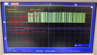
  • I monitored the serial communication bus line after cycling the power and resetting, using my application and example code separately. What does it say about the serial port initialization?

    my application after reset

    my application after cycling the power

    the example code after cycling the power

  • Hi Crane,

    EDIT: typo, I swapped "PC" and "C2000 MCU" in first sentence, fixed that below.

    When you say "cycling the power" do you mean turning off ONLY the [EDIT] C2000 MCU? Does the PC device stay on during this time?

    If that is the case, then the dip in voltage is enough to trigger a break detect in your code, or may be causing other issues. Even the example code picture you showed (third image) has some voltage sag from C2000 device, meaning the power supply may not be fully settled yet. I highlighted this problem section below.

    You may want to provide even longer delay before initialization (enough for your power supply to settle). Maybe 1 full second to start your testing with. Then view the Power supply during startup to determine the lowest time you can safely begin communications with.

    Regards,

    Vince

  • Yes PC device, which is PC with Tera Term, stays on all the time.

    The delay added before Board_init() just delays the time the MCU Tx line goes up. It doesn't help.

    I tried to add the day in the example code and as you said, it works to allow the serial communication start after Tx line is perfectly at high. 

    I think the delay needs to be added right before performing SCI reset SCI_performSoftwareReset() which is in Board_init() in board.c. But this board.c is a derived file. I need to figure out how to do that.

  • Hi Crane,

    If you want, you can put the delay right before the SCI_performSoftwareReset by copying all of the code generated from the board.c file into the main, and then removing the "Board_init()" function.

    Then you can add the delay line and see if this helps.

    I believe it should not be necessary to directly before the SoftwareReset line, because the main issue that we're trying to avoid by adding a delay is the RX line seeing a BRKDT (low signal) while the SCI is still booting up. This delay should be able to go anywhere before the software reset. As long as the softwarereset occurs AFTER everything has settled and RX line is smooth (and the power supplies are settled).

    Basically, you don't want to start SCI until everything is okay in the system. And from the image I mentioned previously, it looks like the power supply is not okay for about 20-30 ms. But your code appears to only be waiting about 5 ms.

    Regards,

    Vince

  • I added 1s delay right before software reset, and it doesn't work.

    And I added 1s delay before Board_init(), also doesn't work. 

    Seems not just about the delay.

  • One more thing, after cycling the power, even reset makes the serial communication transmission to PC doesn't work any more. Before cycling the power, reset works.

  • Hi Crane,

    Thanks for the follow up. Then this is possible that something else is triggering an error and not letting the SCI communicate. Can you provide the values in all of the SCI error registers during the error case?

    I would think this would still be a BRKDT, but it's possible something else may be flagged. If nothing is flagged as an error in the SCI yet it will not communicate, then this may be a system-level issue, and I would request that you attempt to toggle a GPIO instead of the SCI to see if ANY output is possible after reset.

    Regards,

    Vince

  • Thank you Vince.

    What is the SCI error registers? The error occurs only after cycling the power and can't be observed when using the debugger.

    It might be relevant to both the initialization and the application. I replaced the application after the system initialization, including SCI, in the example project and see weird things. I will update here when there is some kind of conclusion.

    The program works after either cycling the power or reset. Even MCU can receive the keyboard input from PC. Just not work in sending info to PC to display.

  • Hi Crane,

    The SCI error register would be the SCIRXST register. If you could read that register and the following registers, that will help to debug the status of the SCI module during this error:

    SCICCR

    SCICTL1

    SCICTL2

    SCIRXST

    Please read these registers and provide their values.

    Regards,

    Vince

  • Ok. But, is there any way to get these values when the program is running from flash and the serial communication is not working. 

  • Hi Crane,

    Are you using a debugger? The debugger JTAG comms should not be affected by this if this is truly an SCI issue.

    Regards,

    Vince

  • Yes I am using a debugger which is in the LaunchPad evaluation board.

    Does it work when the program starts from flash? There is nothing that can be seen. Any other way to use the debugger to read these registers?

  • Hi Crane,

    As long as the debugger is connected (regardless of flash or RAM), you can click "connect to target" button which looks like this:

    When you have a device connected, it will not be greyed out.

    You can also start a FLASH debug session by clicking on the build dropdown and choosing CPU1_FLASH instead of RAM.

    Then you can just click the green "Debug" button and start a debug session.

    Regards,

    Vince

  • No, saying "start from flash", I mean the program is already loaded to flash and it doesn't rely on the debugger to start running, instead it runs automatically once the power is turned on. 

    In this scenario, after it is running, if the green debug button is clicked, it starts loading the program again and then wait to start after finish loading.

  • I changed the application and then see the behavior changes after it started after cycling the power or reset comparing to how it behaves right after the program is loaded.

    Now at least it displays something although not as expected. (It should display as in the red circle.)

  • Finally find that the string operation caused the problem.

            msg = "\r\nHello-\0";
    
            char tempMsg[10], newMsg[32]; itostr(tempMsg, loopCounter, 0);
    
    //        strncpy(newMsg, msg, 17); strcat(newMsg, tempMsg);
    
            newMsg[0]='\r'; newMsg[1]='\n'; newMsg[2]='H'; newMsg[3] ='e'; newMsg[4] ='l'; newMsg[5]='l';newMsg[6]='o',newMsg[7]='-'; newMsg[8]= tempMsg[0]; newMsg[9] = tempMsg[1]; newMsg[10]=tempMsg[2];newMsg[11]='\0';
    
            UART_Send(newMsg);

    If the string operations are used, as in the statements which was commented out, the serial transmission from MCU to PC doesn't work. Otherwise it works. Any idea on what the difference is?

  • Hi Crane,

    Two potential main issues here:

    newMsg[32];

    1. newMsg is 32 bytes long and the code above is not filling in the rest of the 32 bytes (only the first 12). There may be bad data in the rest of the bytes which is leading to all of the above being sent when you call "UART_Send".

    newMsg[8]= tempMsg[0]; newMsg[9] = tempMsg[1]; newMsg[10]=tempMsg[2];

    2. itostr may not guarantee the number of bytes. So when you try to read tempMsg[1] and tempMsg[2], it may be incorrect data you are accessing. For example if there's only one integer (like "1") then reading the rest of the bytes may yield bad data.

    Regards,

    Vince

  • Hi Vince,

    1. It won't as the send function will check the end symbol '\0'. As long there is a '\0\ at the end of newMsg, the symbol after that will be ignored.

    2. If the tempMsg has only 1 or 2 valid symbol, it will end with '\0'. Then the send function will recognize that.

    It works when the program runs right after the code is loaded into flash. When you see the picture of the displaying result, the program is part of the information was not output. And it only happens after cycling the power. Somehow it is relevant to the program running from flash or the process of loading the program to flash.

    Thanks!

    Crane

  • Hi Crane,

    This sounds like the issue may reside in the UART_Send command, can you provide the details of that function?

    Also I see you opened a new thread, did you want me to merge the two (are they the same issue)?

    Regards,

    Vince

  • Hi Vince,

    This issue is addressed. The cause is that the .const section where strings are stored is actually put in RAM instead of FLASH. After the power is cycled, these strings are actually blank and there is no information sent to PC.

    You mean this thread: https://e2e.ti.com/support/microcontrollers/c2000-microcontrollers-group/c2000/f/c2000-microcontrollers-forum/1167098/tms320f280040-q1-the-serial-communication-after-disconnecting-reconnecting-the-bus/4391570#4391570? It is a different issue. I would prefer not to be merged with this one.

    Thanks Vince!

    Crane