Other Parts Discussed in Thread: LAUNCHXL-F280039C, , C2000WARE, SYSCONFIG
Hello TI-experts,
I would like to generate symmetrical pwm signals with high resolution, complementary outputs and dead times. I am using the TMS320F280039C on the LAUNCHXL-F280039C.
Without hr-mode my ePWM module seems to work correctly with the required dead time. HR mode without complementarty output signals are working fine too.
I have already checked my configuration of the hr mode by creating an auxiliary output (ePWMxB) which is set if the timer is zero and which is cleared when the counter reachs the period. By doing this I was able to chek the center alignment. Looks fine so far.
But when I try to combine both, the delay of the dead band module are not as expected. The blanking times are unequal.
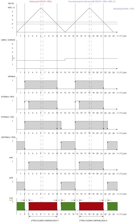
I have created a test case which shows the problem. This is how I configure the ePWM modules:
void init_pwm(void)
{

    // Disables TBCLKSYNC for correct synchronisation of multiple ePWM modules
    EALLOW;
    CpuSysRegs.PCLKCR0.bit.TBCLKSYNC = 0;
    EDIS;

    uint16_t i;
    for(i = 1; i < 4; i++)
    {
        // Time-Base Submodule
        (*ePWM[i]).TBPRD = 600;         // Set timer period
        (*ePWM[i]).TBPRDHR = 0;                 // HR Period

        (*ePWM[i]).TBCTR = 0x0000;              // Clear counter

        (*ePWM[i]).TBCTL.bit.PRDLD = 0;         // Active Period Reg Load from Shadow
        (*ePWM[i]).TBCTL.bit.CTRMODE = 2;       // Up-Down-Count mode
        (*ePWM[i]).TBCTL.bit.FREE_SOFT = 2;     // free run in emulation mode
        (*ePWM[i]).TBCTL.bit.PHSDIR = 1;        // Count up after the synchronization event
        (*ePWM[i]).TBCTL.bit.PHSEN = 0;         // Disable load event when an EPWMxSYNCI input signal occurs
        (*ePWM[i]).TBCTL.bit.HSPCLKDIV = 0;     // Clock ratio / 1
        (*ePWM[i]).TBCTL.bit.CLKDIV = 0;        // Clock ratio / 1

        // Synchronization in- and output
        (*ePWM[i]).EPWMSYNCINSEL.bit.SEL = 0;    // Disables all inputs for this module
        (*ePWM[i]).EPWMSYNCOUTEN.bit.SWEN = 0;   // Disable EPWMxSYNCO at SWFSYNC

        // Counter-Compare Submodule
        (*ePWM[i]).CMPCTL.bit.LOADAMODE = 0;     // Load CMPA when TBCTR = 0
        (*ePWM[i]).CMPCTL.bit.SHDWAMODE = 0;     // enable CMPA shadow mode
        (*ePWM[i]).CMPA.bit.CMPA = 20;  // Set default CMPA value

        // Action-Qualifier Submodule
        // ePWMxA on-time = 2* CMPA  * (1 / 120 MHz)
        // ePWMxB on-time = (1200 - 2 * CMPA) * (1 / 120 MHz)
        (*ePWM[i]).AQCTLA.bit.ZRO = 2;           // Set ePWMxA when TBCTR = 0
        (*ePWM[i]).AQCTLA.bit.CAU = 1;           // Clear ePWMxA when TBCTR = CMPA on up-count
        (*ePWM[i]).AQCTLA.bit.CAD = 2;           // Set ePWMxA when TBCTR = CMPA on down-count

        // ePWMxA on-time = (1200 - 2 * CMPA) * (1 / 120 MHz)
        // ePWMxB on-time = 2* CMPA  * (1 / 120 MHz)
        //(*ePWM[i]).AQCTLA.bit.ZRO = 1;           // Clear ePWMxA when TBCTR = 0
        //(*ePWM[i]).AQCTLA.bit.CAU = 2;           // Set ePWMxA when TBCTR = CMPA on up-count
        //(*ePWM[i]).AQCTLA.bit.CAD = 1;           // Clear ePWMxA when TBCTR = CMPA on down-count


        (*ePWM[i]).DBCTL.bit.HALFCYCLE = 1;     // clock DB counters at half TBCLK rate
        (*ePWM[i]).DBCTL.bit.DEDB_MODE = 0;         // RED to Input A, FED to Input A
        (*ePWM[i]).DBCTL.bit.IN_MODE = 0;
        (*ePWM[i]).DBCTL.bit.OUT_MODE = 3;          // RED to A path, FED to B path
        (*ePWM[i]).DBCTL.bit.POLSEL = 2;            // B path inverted
        (*ePWM[i]).DBCTL.bit.OUTSWAP = 0;           // A path to OutA, B path to OutB
        (*ePWM[i]).DBCTL.bit.SHDWDBFEDMODE = 1;     // FED shandow load mode
        (*ePWM[i]).DBCTL.bit.SHDWDBREDMODE = 1;     // RED shandow load mode
        (*ePWM[i]).DBCTL.bit.LOADFEDMODE = 2;       // Load on TBCTR = 0 or TBCTR = PRD
        (*ePWM[i]).DBCTL.bit.LOADREDMODE = 2;       // Load on TBCTR = 0 or TBCTR = PRD

        (*ePWM[i]).DBRED.bit.DBRED = 10;
        (*ePWM[i]).DBFED.bit.DBFED = 10;

        // Digital-Compare Submodule
        EALLOW;
        (*ePWM[i]).DCTRIPSEL.bit.DCAHCOMPSEL = 3;    // select TRIP4 as Digital Compare A High Input
        (*ePWM[i]).DCACTL.bit.EVT1FRCSYNCSEL = 1;    // DCAEVT1 Force Source is passed through asynchronously
        EDIS;

        // Trip-Zone Submodule
        EALLOW;
        (*ePWM[i]).TZSEL.bit.DCAEVT1 = 1;          // Enable DCAEVT1 as a one-shot trip source
        (*ePWM[i]).TZDCSEL.bit.DCAEVT1 = 2;        // Digital Compare Output A Event 1 Selection: DCAH = high, DCAL = don't care
        (*ePWM[i]).TZCTL.bit.TZA = 2;              // Force EPWMxA to a low state on trip event
        (*ePWM[i]).TZCTL.bit.TZB = 2;              // Force EPWMxB to a low state on trip event
        EDIS;

        if(i == 1)
        {
            // Trip-Zone Submodule
            EALLOW;
            (*ePWM[i]).TZEINT.bit.OST = 1;           // Enable Trip-zone One-Shot Interrupt
            EDIS;
            // Event-Trigger Submodule
            (*ePWM[i]).ETSEL.bit.INTSEL = 0;         // Disables Interrupt when TBCTR = 0
            (*ePWM[i]).ETSEL.bit.INTEN = 1;          // Enable INT
            (*ePWM[i]).ETSEL.bit.SOCAEN = 1;         // Enable EPWMxSOCA pulse
            (*ePWM[i]).ETSEL.bit.SOCASEL = 1;        // Enable EPWMxSOCA  event time-base counter equal to zero
            (*ePWM[i]).ETPS.bit.INTPRD = 1;          // Interrupt on first event
            (*ePWM[i]).ETPS.bit.SOCAPRD = 1;         // EPWMxSOCA on first event
        }
        else
        {
            // Event-Trigger Submodule
            (*ePWM[i]).ETSEL.bit.INTSEL = 0;         // Disables Interrupt when TBCTR = 0
            (*ePWM[i]).ETSEL.bit.INTEN = 0;          // Disable INT
            (*ePWM[i]).ETPS.bit.INTPRD = 0;          // Disable the interrupt event counter
        }


        EALLOW;
        (*ePWM[i]).HRCNFG.all = 0x0;
        (*ePWM[i]).HRCNFG.bit.EDGMODE = 3;          // MEP control of both edges
        (*ePWM[i]).HRCNFG.bit.CTLMODE = 0;          // Duty control mode
        (*ePWM[i]).HRCNFG.bit.HRLOAD = 2;           // Load CMPAHR when TBCTR = 0 or TBCTR = PRD
        (*ePWM[i]).HRCNFG.bit.AUTOCONV = 1;         // Automatic HRMSTEP scaling is enabled

        (*ePWM[i]).HRCNFG2.bit.EDGMODEDB = 3;       // MEP control of both edges (DBREDHR and DBFEDHR)
        (*ePWM[i]).HRCNFG2.bit.CTLMODEDBRED = 2;    // load shadow register when CTR = Zero or CTR = PRD
        (*ePWM[i]).HRCNFG2.bit.CTLMODEDBFED = 2;    // load shadow register when CTR = Zero or CTR = PRD

        (*ePWM[i]).HRPWR.bit.CALPWRON = 1;          // Enables MEP calibration logic

        (*ePWM[i]).HRPCTL.bit.HRPE = 1;             // High resolution period enabled
        (*ePWM[i]).HRPCTL.bit.TBPHSHRLOADE = 1;     // Synchronize the high-resolution phase on a TBCTL[SWFSYNC] event
        EDIS;

        (*ePWM[i]).TBCTL.bit.PHSEN = 1;             // load TBPHS from shadow on a TBCTL[SWFSYNC] event
        (*ePWM[i]).TBCTL.bit.SWFSYNC = 1;           // generates a TBCTL[SWFSYNC] event

    }


    EALLOW;
    CpuSysRegs.PCLKCR0.bit.TBCLKSYNC = 1;       // Enable EPWM Time Base Clock gating
    EDIS;


    while(SFO() == 0)
    {
        // Wait until SFO has finished
    }
}
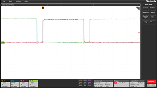
Measurement :
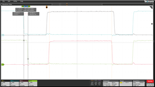
Measurement data:
Channel 1: ePWM[1]: Output A
Channel 2: ePWM[1]: Output B
Channel 3: ePWM[2]: Output A
Channel 4: ePWM[2]: Output B
Epwm clock frequency = 120 MHz
TBPRD = 600
up-down-count mode
RED of ePWM[1] = 10
FED of ePWM[1] = 10
CMPA of ePWM[1] = 20
CMPAHR of ePWM[1] = 32768
RED of ePWM[2] = 10
FED of ePWM[2] = 10
CMPA of ePWM[1] = 20
CMPAHR of ePWM[1] = 0
The alignment of Channel 1 and Channel 3 are as expected. Because I use the up-down-count mode the on-time of Channel 1 is one clock cycle (1 / 120 MHz = 8,33 ns) longer as the on time of channel 3, aligned to the center of both on-times. Channel 3 and Channel 4 are also fine. But the blanking times of ePWM[1] are wrong. As you can see on the cursors time measurement, the difference between the complemntary oututs of the two ePWM modules are one clock cycle, instead of an half clock cycle.
How can I achieve proper behavior of the dead band submodule in hr-mode with complementary output signals?
Thank you in advance.
Reagrds
Stefan