This thread has been locked.

If you have a related question, please click the "Ask a related question" button in the top right corner. The newly created question will be automatically linked to this question.

TMS320F28388D: CLB will not work if ePWM1 is configured

Part Number: TMS320F28388D
Other Parts Discussed in Thread: SYSCONFIG

Hello, I am facing a problem with CLB and ePWM modules. I had configured CLB to create an auxiliary clock using CLB TILE4 and I could capture the clock in oscilloscope with the sysconfig standalone project. However, when I integrated the project into a motor control program that configured the ePWM1 module like in the following code, there would be no clock generated anymore. I found that the function InitEPwmTcExample(0) at line 32 was the reason. How could I resolve this confict?

Thanks for taking the time to read this!

#include <Main.h>

volatile struct EPWM_REGS *ePWM[] ={ &EPwm1Regs,
                                     &EPwm2Regs,
                                     &EPwm3Regs,
                                     &EPwm4Regs,
                                     &EPwm5Regs,
                                     &EPwm6Regs,
                                     &EPwm7Regs,
                                     &EPwm8Regs,
                                     &EPwm9Regs,
                                     &EPwm10Regs,
                                     &EPwm11Regs,
                                     &EPwm12Regs };

void ConfigEPWM(void)
{
    EALLOW;
    CpuSysRegs.PCLKCR0.bit.TBCLKSYNC = 0;
    EDIS;
    EALLOW;
    ClkCfgRegs.PERCLKDIVSEL.bit.EPWMCLKDIV = 0;
    EDIS;

    EALLOW;
    EPwm1Regs.TZFRC.bit.OST = 1;
    EPwm2Regs.TZFRC.bit.OST = 1;
    EPwm3Regs.TZFRC.bit.OST = 1;
    EDIS;


    InitEPwmTcExample(0);
    InitEPwmTcExample(1);
    InitEPwmTcExample(2);


    EPwm1Regs.ETSEL.bit.SOCAEN = 1;
    EPwm1Regs.ETSEL.bit.SOCASEL = 1;
    EPwm1Regs.ETPS.bit.SOCAPRD = 1;


    EPWM_disablePhaseShiftLoad(EPWM1_BASE);
    EPWM_setPhaseShift(EPWM1_BASE, 0U);

    EPWM_enableSyncOutPulseSource(EPWM1_BASE, EPWM_SYNC_OUT_PULSE_ON_CNTR_ZERO);

    configurePhase(EPWM2_BASE, EPWM1_BASE, 0);
    configurePhase(EPWM3_BASE, EPWM1_BASE, 0);

    EPWM_setSyncInPulseSource(EPWM2_BASE, EPWM_SYNC_IN_PULSE_SRC_SYNCOUT_EPWM1);
    EPWM_setSyncInPulseSource(EPWM3_BASE, EPWM_SYNC_IN_PULSE_SRC_SYNCOUT_EPWM1);

    EPWM_enablePhaseShiftLoad(EPWM2_BASE);
    EPWM_enablePhaseShiftLoad(EPWM3_BASE);

    EALLOW;

    GpioCtrlRegs.GPAPUD.bit.GPIO0 = 1;
    GpioCtrlRegs.GPAMUX1.bit.GPIO0 = 1;

    GpioCtrlRegs.GPAPUD.bit.GPIO1 = 1;
    GpioCtrlRegs.GPAMUX1.bit.GPIO1 = 1;

    GpioCtrlRegs.GPAPUD.bit.GPIO2 = 1;
    GpioCtrlRegs.GPAMUX1.bit.GPIO2 = 1;

    GpioCtrlRegs.GPAPUD.bit.GPIO3 = 1;
    GpioCtrlRegs.GPAMUX1.bit.GPIO3 = 1;

    GpioCtrlRegs.GPAPUD.bit.GPIO4 = 1;
    GpioCtrlRegs.GPAMUX1.bit.GPIO4 = 1;

    GpioCtrlRegs.GPAPUD.bit.GPIO5 = 1;
    GpioCtrlRegs.GPAMUX1.bit.GPIO5 = 1;
    EDIS;

    EALLOW;
    CpuSysRegs.PCLKCR0.bit.TBCLKSYNC = 1;
    EDIS;

    GPIO_setDirectionMode(84, GPIO_DIR_MODE_OUT); // Enable PWM EN (PWMEN_INV - SN74LVCC3245A) refer to CJ_GPIO.c
    PWM_EN;
}


void InitEPwmTcExample(Uint16 module)
{
    ePWM[module]->TBCTL.bit.CTRMODE = TB_COUNT_UPDOWN;
    ePWM[module]->TBCTL.bit.PHSEN = TB_DISABLE;
    ePWM[module]->TBPHS.bit.TBPHS = 0x0000;
    ePWM[module]->TBCTL.bit.HSPCLKDIV = TB_DIV1;
    ePWM[module]->TBCTL.bit.CLKDIV = TB_DIV1;
    ePWM[module]->TBPRD = 6250;
    ePWM[module]->TBCTR = 0x0000;
    ePWM[module]->AQCTLA.bit.CAU = AQ_CLEAR;
    ePWM[module]->AQCTLA.bit.CAD = AQ_SET;
    ePWM[module]->DBCTL.bit.OUT_MODE = DB_FULL_ENABLE;
    ePWM[module]->DBCTL.bit.IN_MODE = DBA_ALL;
    ePWM[module]->DBRED.bit.DBRED = 660;
    ePWM[module]->DBFED.bit.DBFED = 660;
    ePWM[module]->DBCTL.bit.POLSEL = DB_ACTV_LOC;
    ePWM[module]->CMPA.bit.CMPA = 3124;
}


void configurePhase(uint32_t base, uint32_t masterBase, uint16_t phaseVal)
{
    uint32_t readPrdVal, phaseRegVal;

    readPrdVal = EPWM_getTimeBasePeriod(masterBase);

    if((HWREGH(base + EPWM_O_TBCTL) & 0x3U) == EPWM_COUNTER_MODE_UP_DOWN)
    {
        phaseRegVal = (2U * readPrdVal * phaseVal) / 360U;
    }
    else if((HWREGH(base + EPWM_O_TBCTL) & 0x3U) < EPWM_COUNTER_MODE_UP_DOWN)
    {
        phaseRegVal = (readPrdVal * phaseVal) / 360U;
    }

    EPWM_selectPeriodLoadEvent(base, EPWM_SHADOW_LOAD_MODE_SYNC);
    EPWM_setPhaseShift(base, phaseRegVal);
    EPWM_setTimeBaseCounter(base, phaseRegVal);
}

  • Xin chao Duc,

    I don't see anything within your InitEPwmTcExample function that would cause an issue with initializing the CLB module. Where is the CLB being instantialized and enabled in your new code? I don't see any CLB calls in the code you posted. I don't believe the ePWM would prevent the CLB from working unless there may be a pin/GPIO conflict?

    Are you still using the previous sysconfig file in your motor control program. You will need to at least have a syscfg file in your new project since that is what houses the CLB Tool configurations the generated source files. Also, make sure you are enabling the CLB within your main code

    Regards,

    Peter

  • Xin chao Peter,

    Thank you for quick response!

    Following code are my initialization for CLB. Because the source code are long, I do not include all of them here. I do not use the sysconfig file in my project and just copy the clb_config.c and clb_config.h files generated by sysconfig to my project and compile them.

    Regards,

    Duc

    #include "driverlib.h"
    #include "device.h"
    #include "clb_config.h"
    #include "clb.h"
    
    void main(void)
     {
        //
        // Initialize device clock and peripherals
        //
        Device_init();
    
        //
        // Turn on the module clock.
        //
        Interrupt_disableMaster();
    
        //
        // Initialize PIE and clear PIE registers. Disables CPU interrupts.
        //
        Interrupt_initModule();
    
        //
        // Disable pin locks and enable internal pull-ups.
        //
        Device_initGPIO();
    
        //
        // Initialize the PIE vector table with pointers to the shell Interrupt
        // Service Routines (ISR).
        //
        Interrupt_initVectorTable();
    
        Interrupt_register(INT_SPIB_RX, &spiRxFIFOISR);
    
        ConfigEPWM();
    
        Interrupt_register(INT_SPIB_RX, &spiRxFIFOISR);
    
        Interrupt_enable(INT_SPIB_RX);
    
        Interrupt_enable(INT_SPIB_RX);
        Interrupt_enableMaster();
    
        init();
    
        DEVICE_DELAY_US(800L);
        
        startOperation();
    
        while(1){}
    }
    
    void init(void)
    {
        SysCtl_enablePeripheral(SYSCTL_PERIPH_CLK_EPWM4);
    
        configEPWM4();
    
        setupGPIO();
        configXBAR();
    
        setupPeriph();
    
        SPI_disableModule(SPIB_BASE);
        SPI_disableInterrupt(SPIB_BASE, SPI_INT_RXFF);
    
        SPI_clearInterruptStatus(SPIB_BASE, SPI_INT_RXFF);
        SPI_enableInterrupt(SPIB_BASE, SPI_INT_RXFF);
    
        SPI_enableModule(SPIB_BASE);
    
        GPIO_writePin(34, 0);
    
        GPIO_writePin(32, 1);
    
        SysCtl_delay(2000000L);
    }
    
    void setupGPIO(void)
    {
        GPIO_setMasterCore(6, GPIO_CORE_CPU1);
        GPIO_setPinConfig(GPIO_6_EPWM4A);
        GPIO_setDirectionMode(6, GPIO_DIR_MODE_OUT);
        GPIO_setPadConfig(6, GPIO_PIN_TYPE_STD);
    
        GPIO_setMasterCore(7, GPIO_CORE_CPU1);
        GPIO_setPinConfig(GPIO_7_EPWM4B);
        GPIO_setDirectionMode(7, GPIO_DIR_MODE_OUT);
        GPIO_setPadConfig(7, GPIO_PIN_TYPE_STD);
    
        GPIO_setMasterCore(24, GPIO_CORE_CPU1);
        GPIO_setPinConfig(GPIO_24_SPIB_SIMO);
        GPIO_setQualificationMode(24, GPIO_QUAL_ASYNC);
    
        GPIO_setMasterCore(25, GPIO_CORE_CPU1);
        GPIO_setPinConfig(GPIO_25_SPIB_SOMI);
        GPIO_setQualificationMode(25, GPIO_QUAL_ASYNC);
    
        GPIO_setMasterCore(26, GPIO_CORE_CPU1);
        GPIO_setPinConfig(GPIO_26_SPIB_CLK);
        GPIO_setQualificationMode(26, GPIO_QUAL_ASYNC);
    
        GPIO_setMasterCore(27, GPIO_CORE_CPU1);
        GPIO_setPinConfig(GPIO_27_SPIB_STEN);
        GPIO_setQualificationMode(27, GPIO_QUAL_ASYNC);
    
        GPIO_setMasterCore(32, GPIO_CORE_CPU1);
        GPIO_setPinConfig(GPIO_32_GPIO32);
        GPIO_setDirectionMode(32, GPIO_DIR_MODE_OUT);
        GPIO_setPadConfig(32, GPIO_PIN_TYPE_STD);
    
        GPIO_setMasterCore(34, GPIO_CORE_CPU1);
        GPIO_setPinConfig(GPIO_34_GPIO34);
        GPIO_setDirectionMode(34, GPIO_DIR_MODE_OUT);
        GPIO_setPadConfig(34, GPIO_PIN_TYPE_STD);
    }
    
    void setupPeriph(void)
    {
        Interrupt_register(INT_CLB4, &clb4ISR);
        Interrupt_enable(INT_CLB4);
    
        resetCLB();
    
        initTILE4(CLB4_BASE);
    
        CLB_enableCLB(CLB4_BASE);
    
        //
        // Select Global input instead of local input for CLB IN
        //
        CLB_configLocalInputMux(CLB4_BASE, CLB_IN0, CLB_LOCAL_IN_MUX_GLOBAL_IN);
        CLB_configLocalInputMux(CLB4_BASE, CLB_IN1, CLB_LOCAL_IN_MUX_GLOBAL_IN);
        CLB_configLocalInputMux(CLB4_BASE, CLB_IN2, CLB_LOCAL_IN_MUX_GLOBAL_IN);
        CLB_configLocalInputMux(CLB4_BASE, CLB_IN3, CLB_LOCAL_IN_MUX_GLOBAL_IN);
        CLB_configLocalInputMux(CLB4_BASE, CLB_IN4, CLB_LOCAL_IN_MUX_GLOBAL_IN);
        CLB_configLocalInputMux(CLB4_BASE, CLB_IN5, CLB_LOCAL_IN_MUX_GLOBAL_IN);
        CLB_configLocalInputMux(CLB4_BASE, CLB_IN6, CLB_LOCAL_IN_MUX_GLOBAL_IN);
        CLB_configLocalInputMux(CLB4_BASE, CLB_IN7, CLB_LOCAL_IN_MUX_GLOBAL_IN);
    
        CLB_configGlobalInputMux(CLB4_BASE, CLB_IN0, CLB_GLOBAL_IN_MUX_EPWM1A);
        CLB_configGlobalInputMux(CLB4_BASE, CLB_IN1, CLB_GLOBAL_IN_MUX_CLB_AUXSIG0);
        CLB_configGlobalInputMux(CLB4_BASE, CLB_IN7, CLB_GLOBAL_IN_MUX_EPWM1A);
    
        CLB_configGPInputMux(CLB4_BASE, CLB_IN0, CLB_GP_IN_MUX_GP_REG);
        CLB_configGPInputMux(CLB4_BASE, CLB_IN1, CLB_GP_IN_MUX_EXTERNAL);
        CLB_configGPInputMux(CLB4_BASE, CLB_IN7, CLB_GP_IN_MUX_GP_REG);
    
        XBAR_setCLBMuxConfig(XBAR_AUXSIG0, XBAR_CLB_MUX01_INPUTXBAR1);
        XBAR_enableCLBMux(XBAR_AUXSIG0, XBAR_MUX01);
    
        CLB_selectInputFilter(CLB4_BASE, CLB_IN0, CLB_FILTER_NONE);
        CLB_selectInputFilter(CLB4_BASE, CLB_IN1, CLB_FILTER_RISING_EDGE);
        CLB_selectInputFilter(CLB4_BASE, CLB_IN7, CLB_FILTER_NONE);
    
        CLB_enableSynchronization(CLB4_BASE, CLB_IN0);
        CLB_enableSynchronization(CLB4_BASE, CLB_IN1);
        CLB_enableSynchronization(CLB4_BASE, CLB_IN7);
    
        //
        // Enable Global Interrupt (INTM) and realtime interrupt (DBGM)
        //
        EINT;
        ERTM;
    
        CLB_clearInterruptTag(CLB4_BASE);
    
        //
        // Enable CLB4 OUT0, OUT2
        //
        CLB_setOutputMask(CLB4_BASE, CLB_OUTPUT_00 | CLB_OUTPUT_02, true);
    
        SPI_disableModule(SPIB_BASE);
        SPI_disableLoopback(SPIB_BASE);
    
        SPI_setConfig(SPIB_BASE, DEVICE_LSPCLK_FREQ, SPI_PROT_POL1PHA0,
                      SPI_MODE_SLAVE, 500000, 9);
    
        SPI_clearInterruptStatus(SPIB_BASE, SPI_INT_RX_OVERRUN |
        SPI_INT_RX_DATA_TX_EMPTY | SPI_INT_RXFF |
        SPI_INT_RXFF_OVERFLOW | SPI_INT_TXFF);
        SPI_enableFIFO(SPIB_BASE);
        SPI_setFIFOInterruptLevel(SPIB_BASE, SPI_FIFO_TX3, SPI_FIFO_RX3);
        SPI_setEmulationMode(SPIB_BASE, SPI_EMULATION_FREE_RUN);
        SPI_enableModule(SPIB_BASE);
        SPI_resetTxFIFO(SPIB_BASE);
        SPI_resetRxFIFO(SPIB_BASE);
    
        SPI_enableInterrupt(SPIB_BASE, SPI_INT_RX_OVERRUN |
        SPI_INT_RX_DATA_TX_EMPTY | SPI_INT_RXFF | SPI_INT_RXFF_OVERFLOW);
    }
    
    void startOperation(void)
    {
        EALLOW;
        HWREG(CLB4_BASE + CLB_LOGICCTL + CLB_O_LOAD_EN) |= CLB_LOAD_EN_GLOBAL_EN
                | CLB_LOAD_EN_STOP;
    
        __asm(" RPT #10 || NOP");
        CLB_setOutputMask(CLB4_BASE, CLB_OUTPUT_00 | CLB_OUTPUT_02, true);
        __asm(" RPT #10 || NOP");
        CLB_setGPREG(CLB4_BASE, 0x81);
    
        EALLOW;
    }
    
    void configXBAR(void)
    {
        XBAR_setInputPin(INPUTXBAR_BASE, XBAR_INPUT1, 24);
    }
    
    void configEPWM4(void)
    {
    
        //
        // Set the PWMA and B high as default values of tformat clk.
        // Action on TZ1
        //
        EPWM_setTripZoneAction(EPWM4_BASE, EPWM_TZ_ACTION_EVENT_TZA,
                               EPWM_TZ_ACTION_HIGH);
    
        //
        // Action on TZ1
        //
        EPWM_setTripZoneAction(EPWM4_BASE, EPWM_TZ_ACTION_EVENT_TZB,
                               EPWM_TZ_ACTION_HIGH);
    
        //
        // Forces a Trip Zone event
        //
        EPWM_forceTripZoneEvent(EPWM4_BASE, EPWM_TZ_FORCE_EVENT_OST);
    }
    
    void resetCLB(void)
    {
        CLB_setGPREG(CLB4_BASE, 0);
    
        //
        // Turn OFF the CLB functionality
        //
        EALLOW;
        HWREG(CLB4_BASE + CLB_LOGICCTL + CLB_O_LOAD_EN) = 0;
        EDIS;
    
        //
        // Clear Counters - this will clear counter REGs. Add_shift_on_even_en
        // should be Zero for this to take effect.
        //
        CLB_writeInterface(CLB4_BASE, CLB_ADDR_COUNTER_0_LOAD, 0x0);
        CLB_writeInterface(CLB4_BASE, CLB_ADDR_COUNTER_1_LOAD, 0x0);
        CLB_writeInterface(CLB4_BASE, CLB_ADDR_COUNTER_2_LOAD, 0x0);
    
        CLB_setOutputMask(CLB4_BASE, 0, false);
    
    }
    

  • Hi Duc,

    The subject matter expert is out of office and will be back on 11/2. Please expect a delay in response

    Best,

    Uttam

  • Hello,

    while I worked with the CLB unit, I made the experience, that you cannot use a PWM channel in the CLB if you use the PWM unit as PWM. If you like to use channel B of the ePWM1 Module as output of your CLB TILE, It'll only work if you don't use the ePWM1 Module as PWM.

    In my Project I wanted to use the channel B of the ePWM6 Unit as output of my CLB-TILE 6 and I wanted to use the channel A as PWM Signal Generator. The CLB output did only work if I didn't use the ePWM6 as a PWM.

    So, if I am not wrong, you can't use a PWM channel in your CLB and use the other channel for PWM applications.

    Best regards,

    Christian

  • Xin chao Duc,

    In your previous standalone code where you were able to generate the clock output, did you use the same process of transferring over the generated CLB source files or did you have a sysconfig file directly. I have heard of occasional build issues from customers who did similarly.

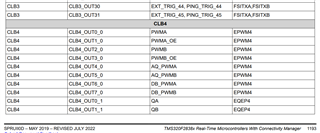
    Thank you for providing your code. To help me clarify your issue, you are saying that you are using CLB4 and EPWM4 to generate the clock output correct? Refer to the below table from the TRM which shows the peripheral output override table for CLB4. 

    And then you say that when you configure EPWM1, you are unable to see any output on the originally configured EPWM4. Is my understanding correct?

    Regards,

    Peter

  • Hi Christian,

    I see what you are saying. A solution to this would be to route both channels of the EPWM module being used into the CLB. For the EPWM channel which you are just wanting to use as a PWM, you can connect the input directly to the CLB output, essentially passing through the signal. You will still have access to the EPWM submodules since the pass through brings out the EPWM output directly

    Regards,

    Peter