This thread has been locked.

If you have a related question, please click the "Ask a related question" button in the top right corner. The newly created question will be automatically linked to this question.

F28M35H52C: CAN LEC reports Bit1 Error during arbitration

Part Number: F28M35H52C
Other Parts Discussed in Thread: CONTROLSUITE

I've been playing with the can_loopback example for the M3 core from controlSuite v202.

I've loaded it on our custom board which has the CAN modules connected to ISO1050DUB transceivers.

I commented out the lines that set up loopback and I have instead connected them together, forming a simple bus at 500 kbps with only the two CAN modules as nodes.

So I have one node sending messages and another receiver them. That works fine.

However, if I unplug the receiving end, I don't see the transmitter's error counter incrementing.

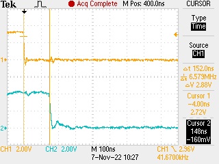
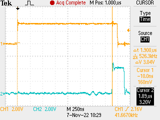
I had an oscilloscope monitoring the CAN_H - CAN_L voltage on the bus.

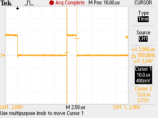
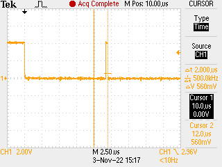
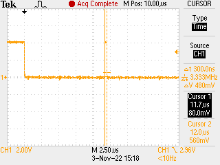
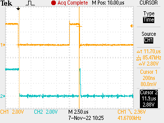
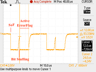
I've attached the annotated screenshot below (recessive bits as high level, dominant as low level). Note that it's at 500 kbps, resulting in 2 µs bits, which corresponds to the smallest time ticks on the oscilloscope screenshot.

One can see the Start of Frame (SoF) followed by four of the initial ID bits (all 0, as the ID was 0x10), which then demanded a stuffing bit 1. It takes too long for the change of levels, causing the monitored bit to be different from the transmitted one and causing the transmitter to send an Error Frame (active error flag, 6 dominant bits).


This scenario in itself is no problem, as the bus had no terminating resistors, so this kind of problem would be expected, as far as I can tell.

I could also then understand the reason why the transmitter error counter wasn't incremented, from CAN 2.0B specs: a stuff error was detected, which triggered an error flag to be sent. However, that happened during arbitration and for a bit which should've been recessive, but was monitored as dominant.

However, the example had an interrupt set up to read the status register through a CANStatusGet() call. The value returned was 4, meaning a "Bit1 Error": 

During the transmission of a message (with the excep-tion of the arbitration field), the device wanted to send a recessive level (bit of logical value '1'), but the monitored bus value was dominant. (SPRUH22I)

The highlighted exception above is in agreement with CAN 2.0B specs (monitoring a dominant bit during transmission of a recessive bit is not a bit error if it happens in arbitration) and means LEC should've read as 1 ("Stuff Error") instead, if I understand correctly. Do I?

  • Hi,

    Thank you for your question. Please expect a reply within the next week.


    Regards,

    Vince

  • I don't see the transmitter's error counter incrementing.

    Under normal circumstances, this should cause an Acknowledge error (ACKE), since there is no other node to provide the ACK. The TEC should increment all the way to128 and stop there. Node will not go bus-off. 

    What is the behavior if you include the termination resistors?

  • If I include the termination resistors, the behavior is as you've described:

    • transmission error is incremented up to 128 and stops;
    • LEC reads 3: ACK error;
    • additional flags raised as indicated by CANStatusGet(): EWarn and EPass (BOff not raised).

    My question is given that a recessive stuffing bit was monitored by the transmitter as dominant during arbitration (as indicated by the oscilloscope screenshot and by the fact that TEC wasn't incremented even though transmission failed) shouldn't LEC have indicated "Stuff Error" instead of "Bit1 Error"?

    I get that, except for the value indicated by LEC, the CAN module is behaving as it should. It's just a matter of whether or not I understood its behavior and correctly interpreted what was happening in this scenario. The value indicated by LEC caused some confusion as I was trying to piece together what was happening.

  • Hi Andre, Hareesh is the best person to continue supporting this thread but unfortunately, he is out of the office for the next few days.  I'm sorry for the inconvenience but you should hear back from him by Thursday.

  • One can see the Start of Frame (SoF) followed by four of the initial ID bits (all 0, as the ID was 0x10), which then demanded a stuffing bit 1.

    Stuff bit is inserted after 5 consecutive bits of the same value and not 4 as you mentioned.

    During arbitration, a transmitted recessive bit may be read back as dominant (because some other node could have driven the bus low), which will not trigger an error frame. 

    Not sure why you are testing an unterminated bus. Not only would that mess up the rise/fall times, it would introduce errors due to signal reflections. If your objective is to just create an error condition, it is OK. You may want to look at www.ti.com/lit/SPRACQ3 for a more deterministic way to inject errors.

  • Hello, thank you for your reply.

    The stuff bit indeed happened after 5 consecutive bits of the same value (dominant). The first dominant bit was the Start of Frame, which was then followed by the 4 first ID bits, all dominant: 5 dominant bits in total.

    Regarding the matter of testing an unterminated bus, it was not the test scenario per se that prompted me to seek help. I was just performing a sanity check by disconnecting the cable and reading the CAN module status as I was familiarizing myself with the example.

    Upon verifying the electrical signal, it became a matter of understanding the CAN module behavior, specifically the LEC field in the Error and Status register (CAN ES), when a bit transmitted as recessive is monitored as dominant during the arbitration field.

    I.e., regardless of the scenario that caused it, why does a bit transmitted as recessive and monitored as dominant during the arbitration field cause LEC to indicate "Bit1 Error"? As mentioned in the original post, what I understood from CAN 2.0B specs is that this is not a BIT ERROR. As you said, it should not trigger an error frame (consistent with what I observed).

    In the scenario I showed, a stuff error is most likely what caused the error frame, which would explain the TEC not incrementing.

    I do appreciate the link to SPRACQ3, thank you, I was not aware of that document.

  • The stuff bit indeed happened after 5 consecutive bits of the same value (dominant).

    You are correct. I missed the SOF.

    why does a bit transmitted as recessive and monitored as dominant during the arbitration field cause LEC to indicate "Bit1 Error"?

    I agree that should not happen. Did you capture both CANTX and CANRX pin activity in the scope to verify your assumption about the prop delays are indeed correct?

  • It is not clear to me what you mean by "my assumption about the prop delays" and whether they are correct. Do you mean if I have checked whether specific bit timing configurations such as the propagation time segment are correct? If that's the case, I have not gone into bit timing details, relying instead on a simple call to CANBitRateSet().

    I see now that CAN BTR reads as 0x344E, with CAN_CLK=75 MHz, meaning 500 kbps, tq = 0,2 µs, bit time = 2 µs, TSEG1 = 1 µs, TSEG2 = 0,8 µs and SJW = 0,4 µs.

    Here are oscilloscope screenshots of the same scenario, but on CANTX:

    And on CANRX (not taken simultaneously to the CANTX screenshot):

    Here's a second screenshot of CANRX, same as above, only moving "Cursor 1" to show the rising time.

    It seems to me CANRX was indeed raised too close, only 300 ns, to the next bit time.

  • By prop delay, I meant the "bus propagation delay". That is the reason I suggested capturing the CANTX and CANRX pins on the same scope shot. 

    On a different note, I am a bit lost as to what we are after here and what information you are expecting from me. This module has been conformance tested by a 3rd party to ensure it conforms to the CAN protocol spec. This includes not just normal operation of the device, but also the module behavior under various error conditions. 

  • Hello. Thank you for replying.

    I appreciate your help and I realize non conformity is the least likely cause for this behavior. I am not an expert in the matter and my hopes in posting here were that someone would be able to clarify to me the behavior I'm seeing or point out the mistakes in my interpretation.

    I'm sorry for the previous scope shots. Here are new ones, simultaneously capturing both CANTX (CH1) and CANRX (CH2) pins under the same conditions as before (node alone connected to an unterminated bus, or a stub).

    Higher res shot of the recessive->dominant transition:

    Higher res shot of the dominant->recessive transition:

    I can see the importance of these shots in understanding why a bit that should be recessive was monitored as dominant and vice-versa.

    Going back to my question below, do these help in clarifying that "a bit transmitted as recessive and monitored as dominant during the arbitration field" is actually happening here?

    why does a bit transmitted as recessive and monitored as dominant during the arbitration field cause LEC to indicate "Bit1 Error"?

    I agree that should not happen.

  • "a bit transmitted as recessive and monitored as dominant during the arbitration field" is actually happening here?

    I think the last scope shot shows that.