This thread has been locked.

If you have a related question, please click the "Ask a related question" button in the top right corner. The newly created question will be automatically linked to this question.

LAUNCHXL-F280049C: LAUNCHXL-F280049C

Part Number: LAUNCHXL-F280049C
Other Parts Discussed in Thread: BOOSTXL-DRV8320RS, C2000WARE, DRV8320

Hello.

I have a LAUNCHXL-F280049C with BOOSTXL-DRV8320RS  and trying to complete all steps of InstaSPIN-FOC for F28004xC Lab Guide but I’m stuck at is02_offset_gain_cal (Offset/Gain calibration with CPU).

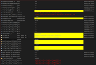
When I set motorVars.flagEnableSys to 1 I don’t have any PWM compare register (CMPA) values in Expressions watch window. Instead I have a „bitfield ‘bit’ not found at ((EPwm1Regs).CMPA).bit, ((EPwm2Regs).CMPA).bit and ((EPwm3Regs).CMPA).bit errors and final offset value is not updated in motorVars.offsets_I_A and motorVars.offsets_V_V after I set flagEnableOffsetCalibration value from 1 to 0.

In the attachment there is a screenshot of my Expression watch window with these errors.

 I using Code Composer Studio Version: 12.1.0.00007 with C2000Ware_MotorControl_SDK_4_01_00_00. And tried to work on two different computers, one with Windows 11 Pro and one with Windows 10 Pro. The problem is the same of both of them.
  • Hi Janusz,

    FYI the CCS12 is not backward compatible to Win10. Did you also load the correct *.asp script file for the debug watch window lab-2? You have to drill down the tree into a daunting search for the /Debug script files directory.

  • Hi GI.

     On my Win 10 machine I have CCS version 12.0.0.00009, on Win 11 machine I have 12.1.0.00007 CCS version but problem occurs in both machines.

     Project is imported to CCS from here: C:\ti\c2000\C2000Ware_MotorControl_SDK_4_01_00_00\solutions\boostxl_drv8320rs\f28004x\ccs\sensorless_foc\is02_offset_gain_cal_eabi.projectspec and variables are imported from here: C:\ti\c2000\C2000Ware_MotorControl_SDK_4_01_00_00\solutions\common\sensorless_foc\debug\is02_offset_gain_cal.js

  • Maybe it was Windows 7 that CCS 12 cannot be installed.  It looks like the DRV8320RS is not installed on the selected booster headers select top of user.h. Could DRV offset by row of header pins, if working in dark area it can happen. You changed lab2 project properties to run from flash memory?

  • Yes, CCS 12 is not compatible with Win 7.

    Should I change something in user.h header file to have DRV8320RS properly working?

    In lab2 I run project from RAM.

     I just imported lab2 into CCS and don’t change enything. Just tried to debug running it from RAM.

  • Just tried to debug running it from RAM

    The user lab guide recommends to change project properties all other labs to flash memory.

    Should I change something in user.h header file to have DRV8320RS properly working?

    Past we had to comment out the booster headers define, for DRV not installed, look top user.h. Recall both sites were defined in earlier SDK version. So hal.c should color over the alternate booster headers not being used, if define is working. After lab 2 you have to ID the motor in lab 5 adding you own motor name define. Check ADC max voltage, current values they should be close to correct <45vdc supply 42 amps for imported DRV8320RS project files.

    Best of luck to you Relaxed

  • OK, when I  switched from RAM to Flash and run the lab 2 in Debug mode, and after I set motorVars.flagEnableSys to 1 I have these messages on console:

    C28xx_CPU1: JTAG Communication Error: (Error -1044 @ 0x0) The debug probe reported an error. Confirm debug probe configuration and connections, reset the debug probe, and retry the operation. (Emulation package 9.9.0.00040)

    C28xx_CPU1: Failed to remove the debug state from the target before disconnecting.  There may still be breakpoint op-codes embedded in program memory.  It is recommended that you reset the emulator before you connect and reload your program before you continue debugging

  • GI I have another question. You mention to disable defines in user.h file, so, please take a look at these settings. Are they OK In case DRV is connected to Site 1:

     #define BOOSTX_to_J1_J2     0

    #define BOOSTX_to_J5_J6     1


    #define BOOST_to_LPD        BOOSTX_to_J1_J2

    //#define BOOST_to_LPD        BOOSTX_to_J5_J6

  • Recalling I used Site 2 to see LEDS under DRV more easily and keep the power supply, motor phases far away from the MCU. S6 was mounted upside down to reroute GPIO 28/29 to BP.  Don't forget to pull JP2 strap off +3v3 so DRV provides launch pad 3v3, not USB buck regulator. 

  • To have DRV on site 2:

    - JP2 – off

    - S6 – ON or OFF?

    - how about JP8?


    Did you change other JP? Did you change something in code to have DRV on site 2 working?


  • S6 to BP or UART? You can verify GPIOs are on Site 2 with DMM ring out too MCU pins. Check hal.c GPIO assigned for the DRV user LED and DRV fault pin has input defined top of setupPWMs() XBAR. JP8 to J5 provide +3v3 to Lauch pad via DRV and +5v J7(on) can have NEXFET cooling fan. Must power fan via USB JP3(on) +5v, JP9(off) buck regulator too low current for most 10mm +5v fans.  

    BTW did the launch pad demo print TI logo to PC screen? Default S6 should have been set UART SCIA for demo, can be switched alternate GPIO's for XDS110 VCOM when using site 2 for DRV. Check PDF Launch Pad User Guide, tables 3 & 4 for proper switch settings and verify hal.c has correct site ADC inputs. TI should have fixed any ADC input pin issues (SDK4.0) but check to be sure DRV is placed on either BP site.

    /cfs-file/__key/communityserver-discussions-components-files/171/TI_2D00_DRV8320-BoostXL-F280049C-QuickStart.pdf 

  • Please don't change anything in the example lab, and follow the lab user's guide to run the related example lab.

    1. Install the BOOSTXL-DRV8320RS on site 1 (J1/J3 & J4/J2) of LAUNCHXL-F28004x.

    2. Add a DC power supply to BOOSTXL-DRV8320RS as the lab user's guide for running this lab.

  • Please don't change anything in the example lab,

    Users have to select the desired booster Site 1 or 2 for the DRV via user.h or hal.c defaults to Site1.  The poster was not changing anything in the example LABS only checking project properties Lab 2 used Flash memory as the LAB guide recommends.

  • PWM works from the very beginning but at zero revolutions.
    I can feel the motor vibrating as I want to turn the axle.
    This means the drver is working but there is nothing they can do.

    When I set motorVars.flagEnableSys to 1 I don’t have any PWM compare register (CMPA) values in Expressions watch window. Instead I have a „bitfield ‘bit’ not found at ((EPwm1Regs).CMPA).bit, ((EPwm2Regs).CMPA).bit and ((EPwm3Regs).CMPA).bit errors and final offset value is not updated in motorVars.offsets_I_A and motorVars.offsets_V_V after I set flagEnableOffsetCalibration value from 1 to 0.

  • C28xx_CPU1: JTAG Communication Error: (Error -1044 @ 0x0) The debug probe reported an error. Confirm debug probe configuration and connections, reset the debug probe, and retry the operation. (Emulation package 9.9.0.00040)

    I forgot to mention check project emulator XML file folder, make sure debug emulation set for 2 wire mode in XDS110 advanced tab. CCS may have placed another XDS110 XML in the project root when changing from RAM to Flash memory.

    It's not advised to put XDSxxx XML file in a project folder for that reason. You can delete the RAM folder after switching project to Flash or just exclude via project properties and any other XML files in the project root. Good practice is to clean the project and recompile after switching from RAM to Flash.

  • When I set motorVars.flagEnableSys to 1

    Same issue shown in posted picture above is very strange but noticed you selected eabi.lib lab version. I could not get the earlier versions of labs to compile via eabi.lib and left it as legacy coff.lib. Wonder if the eabi.lib Lab2 is giving CCS12 any warnings during compile?  Perhaps import LAB2 (coff.lib) version CCS12 and see if the same issues with CMPA bits not showing any data.

    I can feel the motor vibrating as I want to turn the axle.
    This means the drver is working but there is nothing they can do.

    Lab2 offset calibration the motor may vibrate but only for short while, shaft(axel) is not supposed to spin. The Instaspin support guide suggest you can reduce R/L 300Hz frequency in user.h if motor is buzzing loudly or getting hot in LAB5 motor ID.  Literature Number: SPRUHJ1I JANUARY 2013 – REVISED OCTOBER 2021

  • In "is02_offset_gain_cal_eabi" lab, you don't need to connect the motor to the BOOSTXL-DRV8320RS, just need to add a DC power supply like +24V.

    You should monitor the EPWM6, EPWM5, and EPWM3 that are for site 1. Add the following variables to the Expressions watch window.

    EPwm6Regs.TBPRD

    EPwm6Regs.CMPA.CMPA

    EPwm5Regs.CMPA.CMPA

    EPwm3Regs.CMPA.CMPA

  • Hello  and @GI.  and I working on this project.
    I started over "is02_offset_gain_cal_eabi" lab and placed BOOSTXL-DRV8320RS on Site 1. I don't change anything in code and don't make any hardware modifications. Then i put:

    EPwm6Regs.TBPRD

    EPwm6Regs.CMPA.CMPA

    EPwm5Regs.CMPA.CMPA

    EPwm3Regs.CMPA.CMPA

    into Expressions watch window and run Debug from Flash and here are results:

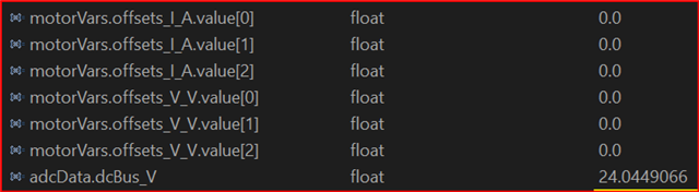
    As you can see I have some values in PWN registers but motorVars.offsets_I_A and motorVars.offsets_V_V variables are not calculated after i switch flagEnableOffsetCalibration from 1 to 0.

    The lab doc said:

    Once finished, change the “flagEnableOffsetCalibration” value from 1 to 0 to complete offset
    calibration. The final offset value will be updated in motorVars.offsets_I_A and
    motorVars.offsets_V_V, shown in Figure 25

  • Just re-tested this lab, seems like it works well.

    1. Install BOOSTXL-DRV8320RS on site 1 of LAUNCHXL-F280049C. Add a 24V DC power supply to BOOSTXL-DRV8320RS.

    2. Build and load the "is02_offset_gain_cal_eabi" project.

    3. Run the lab, and  set "motorVars.flagEnableSys" to "1".

    4. Monitor the ADC results as below

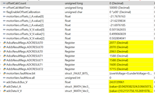
    5. Change "flagEnableOffsetCalibration" from "1" to "0", the offset calibration values will be as below when offsetCalcCount equal to "0"

    Please check if "motorVars.faultNow.all" equals to "0" after you set "motorVars.flagEnableSys" to "1". If not, there are something wrong on the kits you used.

  • When I set flagEnableOffsetCalibration" from "1" to "0" the offsetCalcCount variable is not equal to "0" but has different value. Each time I run this project the "offsetCalcCount" variable has random values after I set flagEnableOffsetCalibration" from "1" to "0".

    As for "motorVars.faultNow.all" variable... When I change "motorVars.flagEnableSys" to "1" the value of "motorVars.faultNow.all" variable is "0" BUT after a while (couple seconds) this value changes to "16".

    UPDATE:

    I switched to another LAUNCHXL-F280049C which I have and the variable "motorVars.faultNow.all" has "0" but offsetCalcCount variable has  "23819" value and newer equals "0".

    I have Code Composer Studio Version: 12.1.0.00007 with C2000Ware_MotorControl_SDK_4_01_00_00. Working on Windows 11 Pro.

  • When you set flagEnableOffsetCalibration" from "1" to "0", the "offsetCalcCount " equals to " offsetCalcWaitTime" (50000) and count down to "0", and then motorVars.offsets_I_A.value[n] and motorVars.offsets_V_V.value[n] will be updated.

  • HI Wojciech,

    "0" BUT after a while (couple seconds) this value changes to "16".

    One over bus voltage inside offset calculation function causes CCMP to trip fault each and every time. You can add automatic clearing fault flag 16 to 0, seems to work ok for me. Curious what library version of SDK are you compiling, legacy coff.lib or eabi.lib? 

        void runOffsetsCalculation(void)
    {
        uint16_t cnt;
        float32_t Vin;
        float32_t invVdcbus;
        volatile static uint32_t Count;
          	//
            // set to the half of inverse dc bus voltage
            // 0.04761904761904761904761904761905
            invVdcbus = 1.0f / adcData.dcBus_V;//1.0f
      
            // enable the PWM
            HAL_enablePWM(halHandle)
          	
          	/* Clear DACH/L latches and any
          	 * Trip Zone CBC/OSHT fault flags */
            /* Has fault bits need clearing */
            if(motorVars.faultNow.all != 0)
      		{
               	/* Clear DACH/L lathes
              	 * and Trip Zone OSHT faults */
              	HAL_clearPWMfaults(halHandle);
              	/* clear fault status bits */
              	motorVars.faultNow.all = 0;
              	SCIprintf(">> OffsetFaults \n");
              	/* Clear DACH/L lathes
              	 * and Trip Zone OSHT faults */
              	HAL_clearPWMfaults(halHandle);
              	//
              	SCIprintf(">>ClearAllFaults \n");
    			// enable the PWM
    			HAL_enablePWM(halHandle);
      		}
      		
    //hal.h:
    
    //! \brief	Clears Tripzone & CMPSSx latched devices
    //! \details    Clears A/B fault flags of the EPWM peripheral which will allow
    //!             the power switches to be controlled. Clears TzFlags and
    //!				CMPSS High/Low digital filter output latch/s
    //! \param[in]  handle  The hardware abstraction layer (HAL) handle
    static inline void HAL_clearPWMfaults(HAL_Handle handle)
    {
    	 HAL_Obj *obj = (HAL_Obj *)handle;
    
        // SW clear high comparator digital filter output latch
        CMPSS_clearFilterLatchHigh(obj->cmpssHandle[0]);
        CMPSS_clearFilterLatchHigh(obj->cmpssHandle[1]);
        CMPSS_clearFilterLatchHigh(obj->cmpssHandle[2]);
        // SW clear low comparator digital filter output latch
        CMPSS_clearFilterLatchLow(obj->cmpssHandle[0]);
        CMPSS_clearFilterLatchLow(obj->cmpssHandle[1]);
        CMPSS_clearFilterLatchLow(obj->cmpssHandle[2]);
    
       // Force clear CBC/OST asserted flags.
    	EPWM_clearTripZoneFlag(obj->pwmHandle[0], HAL_TZ_FLAGS_ALL);
    	EPWM_clearTripZoneFlag(obj->pwmHandle[1], HAL_TZ_FLAGS_ALL); 
    	EPWM_clearTripZoneFlag(obj->pwmHandle[2], HAL_TZ_FLAGS_ALL); 
    
    	return;
    }// end of HAL_clearPWMfaults() function


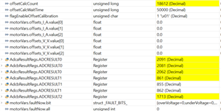
  •  this is what I have before set "motorVars.flagEnableSys" to "1":

    Next, when I enable "motorVars.flagEnableSys" to "1" I have this:

    As you can see "offsetCalcCount" has some value but this value is changing - increases and decreases (for example: "12828", "34701", "19104") and when I change "flagEnableOffsetCalibration" from "1" to "0", offsetCalcCount value just stops as you can see below:

    So ""offsetCalcCount" is newer equal to "offsetCalcWaitTime" and newer count down to "0".

    One more thing... I have also this errors in expressions view window:

  • HI GI. My runOffsetsCalculation function is more different than yours, please take a look:

    void runOffsetsCalculation(void)
    {
        float32_t invVdcbus;
        uint16_t cnt;
    
        if(motorVars.flagEnableSys == true)
        {
            //
            // enable the PWM
            //
            HAL_enablePWM(halHandle);
    
            //
            // set the 3-phase output PWMs to 50% duty cycle
            //
            pwmData.Vabc_pu.value[0] = 0.0;
            pwmData.Vabc_pu.value[1] = 0.0;
            pwmData.Vabc_pu.value[2] = 0.0;
    
            //
            // set to the inverse dc bus voltage
            //
            invVdcbus = 1.0f / adcData.dcBus_V;
    
            for(cnt = 0; cnt < USER_NUM_CURRENT_SENSORS; cnt++)
            {
                //
                // reset current offsets used
                //
                motorVars.offsets_I_A.value[cnt] = 0.0;
    
                //
                // run current offset estimation
                //
                FILTER_FO_run(filterHandle_I[cnt],
                              adcData.I_A.value[cnt]);
            }
    
            for(cnt = 0; cnt < USER_NUM_VOLTAGE_SENSORS; cnt++)
            {
                //
                // reset voltage offsets used
                //
                motorVars.offsets_V_V.value[cnt] = 0.0;
    
                //
                // run voltage offset estimation
                //
                FILTER_FO_run(filterHandle_V[cnt],
                              adcData.V_V.value[cnt] * invVdcbus);
            }
    
            offsetCalcCount++;
    
            if(offsetCalcCount >= offsetCalcWaitTime)
            {
                for(cnt = 0; cnt < USER_NUM_CURRENT_SENSORS; cnt++)
                {
                    //
                    // get calculated current offsets from filter
                    //
                    motorVars.offsets_I_A.value[cnt] =
                            FILTER_FO_get_y1(filterHandle_I[cnt]);
    
                    //
                    // clear current filters
                    //
                    FILTER_FO_setInitialConditions(filterHandle_I[cnt],
                                                  motorVars.offsets_I_A.value[cnt],
                                                  motorVars.offsets_I_A.value[cnt]);
                }
    
                for(cnt = 0; cnt < USER_NUM_VOLTAGE_SENSORS; cnt++)
                {
                    //
                    // get calculated voltage offsets from filter
                    //
                    motorVars.offsets_V_V.value[cnt] =
                            FILTER_FO_get_y1(filterHandle_V[cnt]);
    
                    //
                    // clear voltage filters
                    //
                    FILTER_FO_setInitialConditions(filterHandle_V[cnt],
                                                  motorVars.offsets_V_V.value[cnt],
                                                  motorVars.offsets_V_V.value[cnt]);
                }
    
                offsetCalcCount = 0;
                motorVars.flagEnableOffsetCalc = false;
    
                //
                // disable the PWM
                //
                HAL_disablePWM(halHandle);
            }
        }
    
        return;
    } // end of runOffsetsCalculation() function

    I using eabi.lib, C2000Ware_MotorControl_SDK_4_01_00_00.

  • I switched to C2000Ware_MotorControl_SDK_3_00_01_00, the result is the same and here is my Expressions values window:

    "motorVars.faultNow.all" value is "16".

    GI, which version of MoorControlSDK do you use?

  • My runOffsetsCalculation function is more different than yours

     Not really that much different but PWM enable 50% duty was causing fault if single step the code. When I reduce the (invVdcbus = 1.0f / adcData.dcBus_V) scale factor, the CCMP (CBC) stops being fault triggered. The offset function is reentrant has ISR cycle count must reach 50K ISR cycles, PWM is driving during wait. The PWM duty cycle causes voltage spikes, needs a soft start duty cycle routine. 

    I switched to C2000Ware_MotorControl_SDK_3_00_01_00

    Perhaps try import the legacy coff.lib version see if it gives the same results.

  •  I started all over on new machine with clean Windows 10 Pro.

    1. Installed CCS 12.0.0.00009 and C200Ware_MotorControl_SDK_4_01_00_00.

    2. Imported "is02_offset_gain_cal_eabi" into CCS.

    3. Checked Target Connection via "Texas Instruments XDS110 USB Debug Probe".

    4. Switched to FLASH, cleaned and rebuilt project.

    5. I uploaded "is02_offset_gain_cal.js" into Expressions view window.

    6. Hit DEBUG, enabled "Silicon Real-time Mode" and enabled "Continuous Refresh" in Expressions view window, resume project.

    7. Next, I set flagEnableSys from 0 to 1 and flagEnableOffsetCalc from 1 to 0.

    BUT the result is the same as in my previous machine. Final offset value is not updated, offsetCalcCount is newer equal to offsetCalcWaitTime and newer count down to "0" and motorVars.faultNow.all equals 16.

    I don't make any hardware modifications and don't change anything in code. In the attachment you will find my code - without any modifications.

    My board is LAUNCHXL F280049C REVA and DRV8320RS connected to Site 1.

    On my LAUNCHXL F280049C I have:

    1. JP1 - off, JP2 - off, JP3 - off.

    2. JP4 - off, JP5 - off, JP6 - off, JP7 - off

    3. JP8 - off/off, JP9 - off

    I'm using "InstaSPIN Projects and Labs User’s Guide. InstaSPIN-FOC for F28004xC Version 1.00.00.00 from March 2018"

    is02_offset_gain_cal.zip

  • 1. Skip Step 6 above, just click debug and resume to load and run the program.

    2. Don't set "motorVars.flagRunIdentAndOnLine" to "1" in this lab, just set "motorVars.flagEnableSys" to "1".

    3. Add a DC power supply to J6 on BOOSTXL-DRV8320RS, like +24V. 

    4.  Check if the value of motorVars.VdcBus_V equals to the voltage of the DC power supply you added to  BOOSTXL-DRV8320RS.

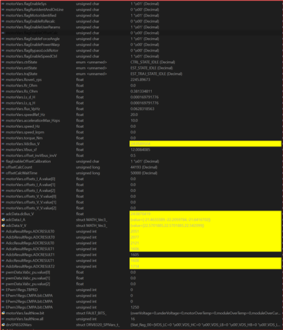
  • OK, I did as you wrote. motorVars.VdcBus_V is equal to the voltage of the DC power supply, so what next should I do/check?

  • motorVars.faultNow.all equals 16.

    Seems like there is something wrong on the BOOSTXL-DRV8320RS or its connection.

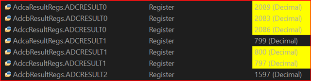
    The values of AdcaResultRegs.ADCRESULT1, AdcbResultRegs.ADCRESULT1 and AdccResultRegs.ADCRESULT1 should be equal to the half of the value of the AdcbResultRegs.ADCRESULT2 when motorVars.flagEnableSys=1 and flagEnableOffsetCalibration=1.

    Can you check if there are PWM outputs on the related GPIO and the MOTA/MOTB/MOTC test points on BOOSTXL-DRV8320RS?

    You may click "CPU reset" and  "Restart" to run the code again to see what happens.

  • 1. Yes, there are PWM outputs on the related GPIO (MOTA/MOTB/MOTC) from 0 to 24V and 40 kHz frequency and values of AdcaResultRegs.ADCRESULT1, AdcbResultRegs.ADCRESULT1 and AdccResultRegs.ADCRESULT1 ARE EQUAL to the half of the value of the AdcbResultRegs.ADCRESULT2 when motorVars.flagEnableSys=1 and flagEnableOffsetCalibration=1.

    2. And on J3 Header (GPIO 23, 24, 25) we have 0.65V (there is no sine wave because motor is cumatated by PWM and have 0 rpm).

    3. As for current and voltage values, please check on the screenshoot, is they are ok?

    4. One more thing, when we touch J3 Header (GPIO 23, 24, 25) by osciloscope we have "16" value on motorVars.faultNow.all.

    5. We checked the BOOSTXL-DRV8320RS hardware without LAUNCHXL F280049C and everything is OK. BOOSTXL-DRV8320RS works, power transistors are OK, 3-phase voltage measurements are OK, 3-phase current measurements are OK.

    6. We don't know why offsetCalcCount varies instead count down to 0 as you mentioned before.

  • 3. As for current and voltage values, please check on the screenshoot, is they are ok?

    It's right.

    6. We don't know why offsetCalcCount varies instead count down to 0 as you mentioned before.

    Normally, the offsetCalcCount will count up to offsetCalcWaitTime (50000), and then reset to "0" when flagEnableOffsetCalibration is changed to 0. And the motorVars.offsets_I_A.value[0/1/2] and  motorVars.offsets_V_V.value[0/1/2] will be updated to a new value.

    Please check the settings below in user.h, make sure that USER_PWM_FREQ_kHz/USER_NUM_PWM_TICKS_PER_ISR_TICK  is less than 20K.

    //! \brief Defines the number of pwm clock ticks per isr clock tick
    //! Note: Valid values are from 1 to 15
    #define USER_NUM_PWM_TICKS_PER_ISR_TICK (1)

    //! \brief Defines the Pulse Width Modulation (PWM) frequency, kHz
    //!
    #define USER_PWM_FREQ_kHz ((float32_t)(15.0)) //15KHz PWM frequency

    You may follow the lab user's guide to run the lab03 and lab04, and see what happens.

  • Hey guys,

    Yesterday was debug single stepping RunOffsetCalculation() and noticed the invVdcbus = value was +NAN most of the time and even had a very high values stepping over.

    After patch adding 2x (float) and make count static it remains very close to expected value 50K counts and CMPSS stop faulting PWM on entry. Best to be static value since  mainISR() is circulating into the call and static decls initialize with 0 value. Make it volatile so the compiler optimization settings don't try to optimize it. Adding (f) after the value did nothing to stop +NAN. Oddly the decal has float32_t but it was not having any effect on the NAN value.

      volatile static float32_t invVdcbus;

    //
    // set to the half of inverse dc bus voltage
    // 0.04761904761904761904761904761905
    invVdcbus = (float)1.0 / (float)adcData.dcBus_V;

  • Need to add the right dc bus voltage to the inverter,  and configure the ADC channel  for dc bus voltage sensing if you are not using the right kit for the example labs.

  • Guys something is wrong.

    I have two: LAUNCHXL-F280049C
    I have a working and electrically checked: BOOSTXL-F8320RS


    We download the software on a clean computer thatI installs automatically.
    We do exactly what is in the documentation.
    We are unable to start Lab2.
    The motor cannot be identified.
    I try a few motors.
    The offsetCalcCount variable changes all the time and does not count down to 0.
    Is there any error information available?
    Why do I have "16" on motorVars.faultNow.all.
    Can I find out what exactly the program stops in Lab2.
    What's out of scope?
    I have made drives on F280027,  F280069 and they work fine, properly, and now I want to start projects on F280049C.
    What are we doing wrong?
    If the program stops in LAB2 how can you know what it stops at. Is it possible ?????????????
    Or on a higher power consumption ...?
    Is it on a high voltage supply ...?
    Is it on the power consumption barrack...?
    We don't know where LAB2 stops.

    Are incorrect libraries automatically downloaded from the server ...?
    Do I need to configure some file...?
    What does "16" mean on motorVars.faultNow.all. ... where it says, DESCRIPTION OF BUGS ...?
    Do others have the same propblem with Ti...?????????????????????

    We've been working for days and nothing has changed. We don't go through Lab2.

    I am asking Texas Instruments and friendly people for help.

  • Hi Janusz,

    We are unable to start Lab2.
    The motor cannot be identified.

    You mean to say Lab5 is for motor Identify. Lab2 offset calculation may cause over current faults. Oddly sometime later after I added the two nonvolatile static floats (posted above code snip), PWM started faulting again even in Lab7 Speed Control.

    The first patch I added above auto clears the CCMP fault flags so offset calculation can progress (offsetCalcCount++) 50K passes. Perhaps fault occurs from an initial inductive spike when PWM-A/B outputs are enabled from high impedance state. I never tested Lab2 without motor on DRV8320 so it may not fault without motor attached. The DRV8320 does not have inductive spike snubber circuits on ABC drive outputs. So inductive spikes can get into CCMP driven by 3 PGA amps and trip an initial PWM fault.

    The 16 seems to show up for any faults, can be cleared in debug expressions box motorVars.faultNow.bit[16]. Expand the array and put 0 where the exception flag shows 1. Mostly for other Labs >2 if a fault occurs driving a motor at peak speed, user.h USER_MOTOR_MAX_CURRENT_A may be set to high. That may also cause trouble in Lab5 motor ID depending on the motor load and user.h settings. If that happens reduce the motor current settings in user.h.

  • We are unable to start Lab2.
    The motor cannot be identified.

    Do you mean lab05 for motor identification? 

    As replied to you above, you don't need to connect the motor to run the lab02, just add the right dc bus power supply on BOOSTXL-F8320RS, dnd don't need to "motorVars.flagRunIdentAndOnLine" to "1"  as well.

    In lab02, the three phase PWM duty will be to 50% to verify the offset calibration, there is no current on the power inverter of BOOSTXL-DRV8320RS.

    Is there any error information available?
    Why do I have "16" on motorVars.faultNow.all.

    You can have a look the bits definition of the :motorVars.faultNow", just add "motorVars.faultNow.bit" in the expression watch window, extend this variable to see which bit is set to "1" to know the fault is triggered. If the motorVars.faultNow.all equal to "16", that means the "moduleOverCurrent" fault is triggered.

    Are incorrect libraries automatically downloaded from the server ...?
    Do I need to configure some file...?

    What do you mean this? Are you using the example labs at "C:\ti\c2000\C2000Ware_MotorControl_SDK_version\solutions\boostxl_drv8320rs\f28004x\ccs"? Or do you make any changes on the example lab?

    You don't need to change anything if you are using the LAUNCHXL-F280049C with BOOSTXL-DRV8320RS kits.

    If you want to run lab05 for motor identification, please don't add any load on the motor for identification, and set the correct identification variables value in the file of user.h according to the specification of the motor, to make sure the motor spin smoothly during Flux measurement and Ls identification states.

    #define USER_MOTOR_RES_EST_CURRENT     (1.0)                               // A - 10-30% of rated current of the motor

    #define USER_MOTOR_IND_EST_CURRENT     (-1.0)                             // A - 10-30% of rated current of the motor, just enough to enable rotation

    #define USER_MOTOR_MAX_CURRENT           (5.0)                               // A - 30~150% of rated current of the motor

    #define USER_MOTOR_FLUX_EST_FREQ_Hz     (20.0)                           // Hz - 10~30% rated frequency of the motor

    We've been working for days and nothing has changed. We don't go through Lab2.

    Seems like the offset calibration is correct on the kits you have. You may try to connect a low voltage motor to the BOOSTXL-DRV8320RS, and try to run the lab04 to see what happens.