This thread has been locked.

If you have a related question, please click the "Ask a related question" button in the top right corner. The newly created question will be automatically linked to this question.

TMS320F2810: Programming via Blackhawk 560

Part Number: TMS320F2810
Other Parts Discussed in Thread: CODECOMPOSER, UNIFLASH,

Hi there,

I try to program a TMS320F2810 using Blackhawk USB560 v2 SystemTrace Debug probe and TI Uniflash or CodeComposer Studio.

In CCS, I installed the Blackhawk drivers (which work well with another Target controller). For uniflash, i installed the Blackhawk package provided here: https://www.blackhawk-dsp.com/support/uniflashv5

The debugger is recognized correctly by both - CCS and Uniflash. I use the standard settings from TMS320F2810 target config:

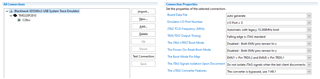
Unfortunately, when I try to connect the target, CCS gives the following error message to me:

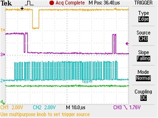
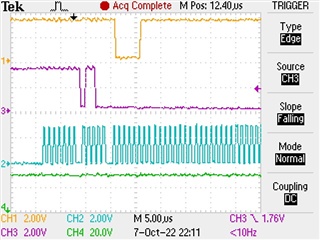
Error connecting to the target:
(Error -183 @ 0x0)
The controller has detected a cable break far-from itself.
The user must connect the cable/pod to the target.
(Emulation package 9.3.0.00058)

I know this error message, I saw it sometimes when I forgot to connect the debug probe to the target. But it is all connected well.
Furthermore, when I try flashing the chip using XDS110 debug probe (using exactly the same wiring and the XDS110 default target config), it works well.

Do you have another idea where to look for the error next? Unfortunately, I am no JTAG-Guru ;)

Best regards,

Chris

  • Hi Chris,

    If certain pins are not connected from the Blackhawk USB560 debugger to the device, you will get this error. There are multiple combinations of unconnected pins that would result in this error instead of a different errors. It is interesting that the XDS110 is able to connect to the target with the same pins connected. Could you share the schematic of the target board? It is possible that some signal that the 560 needs is not connected, while the XDS110 may not need that signal, but I am not sure which signal would fit that description. 

    Best Regards,

    Ben Collier

  • Hi Ben,

    thank you for your reply - sorry for being that late!

    I can provide this stripped-down schematic which focuses on the JTAG part. In our application, we have got another 10 pin Molex connector in between, but I left it out for making it more simple. As you can see, all lines are connected well except for the EMU lines.

    Best regards,

    Chris

  • Hi Chris,

    Do you have access to a oscilloscope so you can probe the signals? You should see the same patterns as I do when I 'Test Connection', with small variability due to the specific debugger. The image below shows TDO (yellow), TMS (purple), TCK (blue), and TRST (green). This is the start of the 'Test Connection' sequence that I captured as a single sequence, triggered on the falling edge of TMS. All signals are 3.3V digital signals.

    If you zoom in more closely, you should see this same pattern at the start. 


    Could you post your oscilloscope captures? Judging from the error, I would suspect some important signals are not being driven at all, and hopefully we could spot this in the oscilloscope captures.  

    Best Regards,

    Ben Collier

  • Hi Ben,
    I do have an oscilloscope and I will measure the requested signals as soon as possible.
    Unfortunately, I will not have access to the programming system before next week, but I will do the measurements directly on Tuesday next week.

    Regards,

    Chris

  • Hi Chris,

    Ok, I will continue to watch this thread for updates.

    Best Regards,

    Ben Collier

  • Hi Ben,
    yesterday I did some measurements on the programming system and was not able to capture a signal on JTAG interface.
    I then tried another Adapter betwenn the 14-pin JTAG and our device and then anything worked well.
    Now I checked the needlebed adapter and well - blackhawk was right when detecting a "cable break": GND line on Pin 2 was not connected.
    Connecting this GND line makes everything work as expected.
    I then wondered why XDS110 was able to program though.. But I measured on the Debugger-side Adapters to 14-pin JTAG and the Adapter on the XDS110 seems to bridge the 4 GND lines by itself, whereas the Adapter on Blackhawk USB-560v2 does not - this explains why I was able to program using XDS110 despite the wrong wiring ;)

    Thank you for your great assistance!

    Best regards,
    Chris

  • Hi Chris,

    That is great to hear, I am glad you have found the solution for your issue!

    Best Regards,

    Ben Collier