This thread has been locked.

If you have a related question, please click the "Ask a related question" button in the top right corner. The newly created question will be automatically linked to this question.

TMS320F28377S-Q1: extract and record the state Parameter when the motor runs

Part Number: TMS320F28377S-Q1
Other Parts Discussed in Thread: CONTROLSUITE, C2000WARE

Hi Team, 

Good day. I am posting this inquiry on behalf of the customer.

"I am doing the stepper-motor control with FOC, which is state control. Now I want to extract and record the state Parameter when the motor runs. The control loop runs once 20 microseconds, and I need a program to acquire a complete set of parameters every 1 or 2 microseconds.

Now I using the Graph Tools, but the sample rate is too low.  

The motor position is reported by an incremental Encode, and the QEP Mode in C2000 calculates the rotor position, then according to the motor equation calculates the rotor position in electrical coordinates. the Code is following

StepsValue is obtained through EQep1Regs.QPOSCNT. then convert into micro steps by a constant( conv_rate),

        StepsValue = (int32)(pulse_value*(float32)conv_rate);

due to 1600 micro-steps per revolution, so the rotor physical angle is calculated as follows

       angle_mech = (int16)(StepsValue % 1600);
 
So the Wave of angle_mech should be saw-tooth, but the Graph displays the reverse.    and the sampling rate is too low.
 
And rotor electrical angle is calculated as follows
 
      angle_elec = angle_mech & 0x001F;

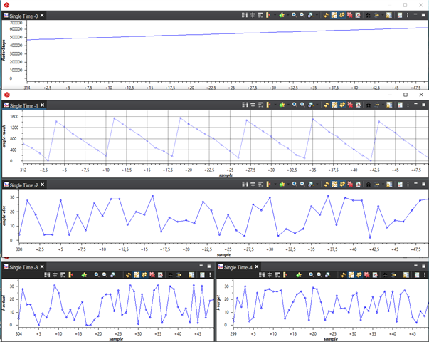
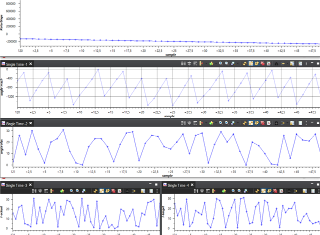
 the Wave should also be saw-tooth, but the Scalar should be in 0-31.

The motor runs counterclockwise as in Graph 1 displayed. And Graph 2 shows clockwise.

Only the StepsValue is right, but the direction of  angle-mech is reverse, and others are chaos"

Please help to advise. Thank you for extending your help.

Kind regards, 

Marvin

  • You can refer to the "Datalog" function in some of the example projects, to store the data into a buffer in RAM memory with a higher frequency, and then use the "Graph Tool" within CCS to view the data.

  • Hi Yanming, 

    Thank you for your prompt response. Please see the feedback from your customer.

    "Could you please give me more details? such as an example code
    I have too little experience with the MCU program.

    If the Data are stored, can I use MATLAB for the graph generation?"

    Please help to advise. Thank you for extending your help.

    Kind regards, 

    Marvin

  • Hi Yanming, 

    Thank you for your response. Please see the feedback from our customer.

    "Still I don't know, how to initialize and configure the Datalog Module, 
    Is there a Manual or an official example code?
     
    I use C2000 Microcontrollers F28377S LaunchPad realize FOC loop, the position sensor is an incremental Encoder.  So the eQEP module read and reports the motor position."

    Please help to advise. Thank you for extending your help.

    Kind regards, 

    Marvin

  • Which example motor control project the customer is using? An example project in controlSUITE? Or in motor control SDK? Or they designed all of codes by themself? Most of the motor control example codes have the datalog function in its project.

  • Hi Yanming, 

    Please see the feedback from the customer.

    I design the code by myself. The Drive board I used is not the Product of TI. 

    In the Technical Reference Manual of TMS320F2837xS Microcontrollers, I find another Module, which I need. But no Datalog Module.
    I created many variables to record the states when the motor runs. They can be used in the control loop. I don't know how can I extract them, without affecting the main process.
     
    that will be better when the record function is parallel.
     
    Should I design a Datalog function by myself? 

    Please help to advise. Thank you for extending your help.

    Kind regards, 

    Marvin

  • You can refer to the example to use the Datalog in controSUITE. The Datalog just stores the variables in a buffer in RAM, and then use graph tool within CCS to show the data in a waveform.

    CONTROLSUITE: http://www.ti.com/tool/CONTROLSUITE

    Example Project: C:\ti\controlSUITE\development_kits\TIDM-SERVO-LAUNCHXS\MonoMtrServo_377s_v1_00_00_00

    Documentation: 

    Sensored FOC of PMSM_XL_BP.pdf in C:\ti\controlSUITE\development_kits\TIDM-SERVO-LAUNCHXS\MonoMtrServo_377s_v1_00_00_00\~Docs

    data_log.pdf in C:\ti\controlSUITE\libs\app_libs\motor_control\drivers\f2803x_v1.1\~Docs

  • Hi Yanming, 

    I really appreciate your help. Please see the feedback from the customer.

    "The new feedback was very helpful.
    But I still have many questions.
     
    First, the example code in data_log.pdf is not identical to Example Project: MonoMtrServo_377s_v1_00_00_00, which causes me to get confused.

    I don't find the two functions either in PDF or in Project.
          void DLOG_4CH_init(DLOG_4CH *);
          void DLOG_4CH_update(DLOG_4CH *);   

    The Codes in Example Project: MonoMtrServo_377s_v1_00_00_00
     
    typedef struct{
        float32 *input_ptr1;
        float32 *input_ptr2;
        float32 *input_ptr3;
        float32 *input_ptr4;
        float32 *output_ptr1;
        float32 *output_ptr2;
        float32 *output_ptr3;
        float32 *output_ptr4;
        float32 prev_value;
        float32 trig_value;
        int16 status;
        int16 pre_scalar;
        int16 skip_count;
        int16 size;
        int16 count;
    }DLOG_4CH_F;
     
    // ****************************************************
    // Initialize DATALOG module
    // ****************************************************
        DLOG_4CH_F_init(&dlog_4ch1);
        dlog_4ch1.input_ptr1 = &DlogCh1;    //data value
        dlog_4ch1.input_ptr2 = &DlogCh2;
        dlog_4ch1.input_ptr3 = &DlogCh3;
        dlog_4ch1.input_ptr4 = &DlogCh4;
        dlog_4ch1.output_ptr1 = &DBUFF_4CH1[0];
        dlog_4ch1.output_ptr2 = &DBUFF_4CH2[0];
        dlog_4ch1.output_ptr3 = &DBUFF_4CH3[0];
        dlog_4ch1.output_ptr4 = &DBUFF_4CH4[0];
        dlog_4ch1.size = 200;
        dlog_4ch1.pre_scalar = 5;
        dlog_4ch1.trig_value = 0.01;
        dlog_4ch1.status = 2;

     I donnot understand the Variable: prev_value, status, and why status=2,
     
    I want to record the Motor Parameters every 1 microsecond, which Variable should be changed? 


    I have read another example Project in controlSUITE; The Codes are identical.
     
    In another Project I found
     
    // Initialize DATALOG module
        dlog.iptr1 = &DlogCh1;
        dlog.iptr2 = &DlogCh2;
        dlog.iptr3 = &DlogCh3;
        dlog.iptr4 = &DlogCh4;
        dlog.trig_value = 0x1;
        dlog.size = 0x00c8;
        dlog.prescalar = 5;
        dlog.init(&dlog);
    // ------------------------------------------------------------------------------
    //    Call the DATALOG update function.
    // ------------------------------------------------------------------------------
       dlog.update(&dlog);
     
    but I cannot locate the initialization and the update function. 
     
     
    After initializing the Model
    I should in main(), Connect inputs to the DATALOG module 
        DlogCh1 = (int16)_IQtoIQ15(Param1);
        DlogCh2 = (int16)_IQtoIQ15(Param2);
        DlogCh3 = (int16)_IQtoIQ15(Param3);
        DlogCh4 = (int16)_IQtoIQ15(Param4);
     
     
    Is that right?

    Can I write that as a subfunction?
     
    Sorry for the many questions"

    Please help to advise. Thank you for extending your help.

    Kind regards, 

    Marvin

  • Technical background should be similar, just add several additional variable to improve the using flexibility. The function is open source, please take a look at the codes that could be easy to understand. You don't need to change the "Status" that will be updated automatically. 

    I want to record the Motor Parameters every 1 microsecond, which Variable should be changed? 

    Call the datalog function (DLOG_4CH_F_FUNC) in a  1-microsecond time interrupt.

    Change the inputs of the DATALOG module as below that could be found in the example project.

    // ------------------------------------------------------------------------------
    // Connect inputs of the DATALOG module
    // ------------------------------------------------------------------------------
    DlogCh1 = motor->rg.Out;
    DlogCh2 = motor->svgen.Ta;
    DlogCh3 = motor->svgen.Tb;
    DlogCh4 = motor->svgen.Tc;

    Please refer to the example in the example project as below step.

    1.  Initialize DATALOG module

    // ****************************************************
    // Initialize DATALOG module
    // ****************************************************
    DLOG_4CH_F_init(&dlog_4ch1);
    dlog_4ch1.input_ptr1 = &DlogCh1; //data value
    dlog_4ch1.input_ptr2 = &DlogCh2;
    dlog_4ch1.input_ptr3 = &DlogCh3;
    dlog_4ch1.input_ptr4 = &DlogCh4;
    dlog_4ch1.output_ptr1 = &DBUFF_4CH1[0];
    dlog_4ch1.output_ptr2 = &DBUFF_4CH2[0];
    dlog_4ch1.output_ptr3 = &DBUFF_4CH3[0];
    dlog_4ch1.output_ptr4 = &DBUFF_4CH4[0];
    dlog_4ch1.size = 200;
    dlog_4ch1.pre_scalar = 5;
    dlog_4ch1.trig_value = 0.01;
    dlog_4ch1.status = 2;

    2. Connect inputs ( the variable you want to monitor/store) of the DATALOG module

    // ------------------------------------------------------------------------------
    // Connect inputs of the DATALOG module
    // ------------------------------------------------------------------------------
    DlogCh1 = motor->rg.Out;
    DlogCh2 = motor->svgen.Ta;
    DlogCh3 = motor->svgen.Tb;
    DlogCh4 = motor->svgen.Tc;

    3. Call DLOG_4CH_F_FUNC() in a timer interrupt as you want interval time.

    // ------------------------------------------------------------------------------
    // Call the DATALOG update function.
    // ------------------------------------------------------------------------------
    DLOG_4CH_F_FUNC(&dlog_4ch1);

  • Hi Yanming, 

    Thank you for the response. Please see the feedback from the customer.

    I have tried setting the datalog function according to the advice, that your engineer has given.
     
    the Step 3. Call DLOG_4CH_F_FUNC() in a timer interrupt as you want interval time.
    How to set up the timer interrupt function?  I have found a "DATALOG_ISR" in F2837xS_DefaultISR.c, use this ISR function? 
     
    and There is another problem.
    refer to the example code, I create a header file, that contains the Variable.
    because my "main" function and subfunction are separate, so the Variable are included separate in main File and in subfunction File, but a error: the Variable is redefine.
     
    #ifndef DLOG_4CH_F_H
    #define DLOG_4CH_F_H
       " typedef struct.."
    #endif /* DLOG_4CH_F_H_ */
     
    This error occurs only for "struct()", if a ordinary Variable is include twice, it will not happen.
     
    at last, which RAM_link should I use?  Generic_RAM_lnk.cmd is also wrong.

    Please help to advise. Thank you for extending your help.

    Kind regards, 

    Marvin

  • How to set up the timer interrupt function?  I have found a "DATALOG_ISR" in F2837xS_DefaultISR.c, use this ISR function? 

    Yes, you can call this datalog function in a ISR function.

    at last, which RAM_link should I use?  Generic_RAM_lnk.cmd is also wrong.

    You should change the .cmd file according to the device directly, or you can use the example .cmd file in C2000Ware for this device. And just change the example .cmd to support the datalog. You can use any RAM if it have enough size for datalog buffer.

    If you haven't had a chance to look at the workshop material, I think this will help you get started using C2000 devices.

    [FAQ] Where can I find training content for C2000 devices?

    [FAQ] C28x Software Tip: Looking for a software example? Documentation?