Hi Team,
There's an issue from the customer need your help:
Hi, I'm reporting an error using 28335/28035 to capture a signal below 500Hz, and I don't know what the specific cause is because it's a stable capture in 500Hz-500kHz capture. I reviewed the book and data manual to see if the counter was not reset to zero in time, but no change was made after configuring the registers, and then I removed the configuration code, which was modified based on the 28335 routine. I hope my friends can teach more. The following are the error symptoms and codes:
void delay_1ms(Uint16 t)
{
while(t--)
{
DELAY_US(1000);
}
}
interrupt void ISRCap1(void)
{
PieCtrlRegs.PIEACK.all = PIEACK_GROUP4;//0x0001赋给12组中断ACKnowledge寄存器,对其全部清除,不接受其他中断
ECap1Regs.ECCLR.all=0xFFFF;//写0XFFFF对CAP1中断清除寄存器进行清除操作
t1= ECap1Regs.CAP1; //赋值
t2= ECap1Regs.CAP2; //赋值
t3= ECap1Regs.CAP3; //赋值
t4= ECap1Regs.CAP4; //赋值
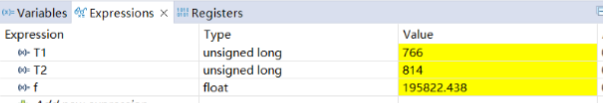
T1=t2-t1;T2=t4-t3;
f = 1/(float)(T1)*150000000;
}
interrupt void ISRCap2(void)
{
PieCtrlRegs.PIEACK.all = PIEACK_GROUP4;//0x0001赋给12组中断ACKnowledge寄存器,对其全部清除,不接受其他中断
ECap2Regs.ECCLR.all=0xFFFF;//写0XFFFF对CAP2中断清除寄存器进行清除操作
t5= ECap2Regs.CAP1; //赋值
t6= ECap2Regs.CAP2; //赋值
t7= ECap2Regs.CAP3; //赋值
t8= ECap2Regs.CAP4; //赋值
T3=t6-t5;T4=t8-t7;
}
ap.c:
#include "bsp_cap.h"
#if DSP28_28335
// ECCTL1 ( ECAP Control Reg 1)
//==========================
// CAPxPOL bits
#define EC_RISING 0x0
#define EC_FALLING 0x1
// CTRRSTx bits
#define EC_ABS_MODE 0x0
#define EC_DELTA_MODE 0x1
// PRESCALE bits
#define EC_BYPASS 0x0
#define EC_DIV1 0x0
#define EC_DIV2 0x1
#define EC_DIV4 0x2
#define EC_DIV6 0x3
#define EC_DIV8 0x4
#define EC_DIV10 0x5
// ECCTL2 ( ECAP Control Reg 2)
//==========================
// CONT/ONESHOT bit
#define EC_CONTINUOUS 0x0
#define EC_ONESHOT 0x1
// STOPVALUE bit
#define EC_EVENT1 0x0
#define EC_EVENT2 0x1
#define EC_EVENT3 0x2
#define EC_EVENT4 0x3
// RE-ARM bit
#define EC_ARM 0x1
// TSCTRSTOP bit
#define EC_FREEZE 0x0
#define EC_RUN 0x1
// SYNCO_SEL bit
#define EC_SYNCIN 0x0
#define EC_CTR_PRD 0x1
#define EC_SYNCO_DIS 0x2
// CAP/APWM mode bit
#define EC_CAP_MODE 0x0
#define EC_APWM_MODE 0x1
// APWMPOL bit
#define EC_ACTV_HI 0x0
#define EC_ACTV_LO 0x1
// Generic
#define EC_DISABLE 0x0
#define EC_ENABLE 0x1
#define EC_FORCE 0x1
#endif // end DSP28_28335
void InitCapl(void)
{
ChoseCap(); // 给CAP分配时钟
InitECap1Gpio(); // 初始化CA1的GPIO
InitECap2Gpio(); // 初始化CA2的GPIO
SetCap1Mode();
SetCap2Mode();
}
void ChoseCap(void)
{
SysCtrlRegs.PCLKCR1.bit.ECAP1ENCLK=1;//enable clock to Cap1
SysCtrlRegs.PCLKCR1.bit.ECAP2ENCLK=1;
//SysCtrlRegs.PCLKCR1.bit.ECAP3ENCLK=1;
//SysCtrlRegs.PCLKCR1.bit.ECAP4ENCLK=1;
//SysCtrlRegs.PCLKCR1.bit.ECAP5ENCLK=1;
//SysCtrlRegs.PCLKCR1.bit.ECAP6ENCLK=1;
}
void SetCap1Mode(void)
{
ECap1Regs.ECCTL1.bit.CAP1POL = EC_RISING;
ECap1Regs.ECCTL1.bit.CAP2POL = EC_RISING;
ECap1Regs.ECCTL1.bit.CAP3POL = EC_RISING;
ECap1Regs.ECCTL1.bit.CAP4POL = EC_RISING;
ECap1Regs.ECCTL1.bit.CTRRST1 = EC_ABS_MODE;
ECap1Regs.ECCTL1.bit.CTRRST2 = EC_ABS_MODE;
ECap1Regs.ECCTL1.bit.CTRRST3 = EC_ABS_MODE;
ECap1Regs.ECCTL1.bit.CTRRST4 = EC_ABS_MODE;
ECap1Regs.ECCTL1.bit.CAPLDEN = EC_ENABLE;
ECap1Regs.ECCTL1.bit.PRESCALE = EC_DIV1;
ECap1Regs.ECCTL2.bit.CAP_APWM = EC_CAP_MODE;
ECap1Regs.ECCTL2.bit.CONT_ONESHT = EC_CONTINUOUS;
ECap1Regs.ECCTL2.bit.SYNCO_SEL = EC_SYNCO_DIS;
ECap1Regs.ECCTL2.bit.SYNCI_EN = EC_DISABLE;
ECap1Regs.ECEINT.all=0x0000;//stop all interrupt
ECap1Regs.ECCLR.all=0xFFFF;//clare all flag
ECap1Regs.ECCTL2.bit.TSCTRSTOP = EC_RUN;// 启动
ECap1Regs.ECEINT.bit.CEVT4=1;// Enable cevt4 interrupt
}
void SetCap2Mode(void)
{
ECap2Regs.ECCTL1.bit.CAP1POL = EC_FALLING;
ECap2Regs.ECCTL1.bit.CAP2POL = EC_FALLING;
ECap2Regs.ECCTL1.bit.CAP3POL = EC_FALLING;
ECap2Regs.ECCTL1.bit.CAP4POL = EC_FALLING;
ECap2Regs.ECCTL1.bit.CTRRST1 = EC_ABS_MODE;
ECap2Regs.ECCTL1.bit.CTRRST2 = EC_ABS_MODE;
ECap2Regs.ECCTL1.bit.CTRRST3 = EC_ABS_MODE;
ECap2Regs.ECCTL1.bit.CTRRST4 = EC_ABS_MODE;
ECap2Regs.ECCTL1.bit.CAPLDEN = EC_ENABLE;
ECap2Regs.ECCTL1.bit.PRESCALE = EC_DIV1;
ECap2Regs.ECCTL2.bit.CAP_APWM = EC_CAP_MODE;
ECap2Regs.ECCTL2.bit.CONT_ONESHT = EC_CONTINUOUS;
ECap2Regs.ECCTL2.bit.SYNCO_SEL = EC_SYNCO_DIS;
ECap2Regs.ECCTL2.bit.SYNCI_EN = EC_DISABLE;
ECap2Regs.ECEINT.all=0x0000;//stop all interrupt
ECap2Regs.ECCLR.all=0xFFFF;//clare all flag
ECap2Regs.ECCTL2.bit.TSCTRSTOP = EC_RUN;// 启动
ECap2Regs.ECEINT.bit.CEVT4=1;// Enable cevt4 interrupt
}
result:

Could you check this case please?Thanks.
Best Regards,
Ben