Other Parts Discussed in Thread: UCC21710, C2000WARE, SYSCONFIG
Hello,
We would like to measure the DC bus using the eCAP module from a PWM pulse train generated by UCC21710.We need some clarification regarding the eCAP module .
Firstly, Can the eCAP measure the duty cycle from a 400 Khz pwm pulse train?, I ask this because looking at the example projects in c2000ware, i see that it is measuring a pwm pulse train of a few kilo hertz.
We tried to simulate the same example , but at a higher frequency, but as we increase the pwm frequency , the duty cycle calculation keeps deteriorating. The variable derivedDT is the result which is calculated from the eCAP module.
__interrupt void INT_myECAP0_ISR(void)
{
    ecap_counter++;
    cap1_count = ECAP_getEventTimeStamp(myECAP0_BASE, ECAP_EVENT_1);    //1st raising edge
    cap2_count = ECAP_getEventTimeStamp(myECAP0_BASE, ECAP_EVENT_2);    //1st falling edge
    cap3_count = ECAP_getEventTimeStamp(myECAP0_BASE, ECAP_EVENT_3);    //2nd raising edge
    cap4_count = ECAP_getEventTimeStamp(myECAP0_BASE, ECAP_EVENT_4);    //2nd falling edge
    derivedDT = (float)(cap2_count-cap1_count)/(cap3_count-cap1_count);
    ECAP_reArm(myECAP0_BASE);
    ECAP_clearGlobalInterrupt(myECAP0_BASE);
    ECAP_clearInterrupt(myECAP0_BASE, ECAP_ISR_SOURCE_CAPTURE_EVENT_4);
    Interrupt_clearACKGroup(INTERRUPT_ACK_GROUP4);

}
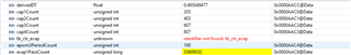
At 10 Khz:

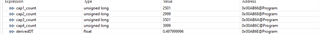
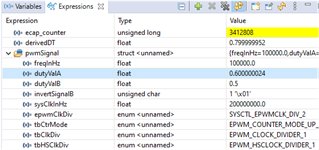
At 100 Khz
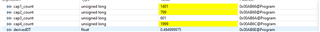
At 500 Khz: