This thread has been locked.

If you have a related question, please click the "Ask a related question" button in the top right corner. The newly created question will be automatically linked to this question.

TMS320F28379D: Reading P0-P7 of PCF8574A I/O Expander

Part Number: TMS320F28379D
Other Parts Discussed in Thread: PCF8574A, C2000WARE, ENERGIA, PCF8574, MSP430G2553, TCA9534

Hi,

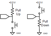
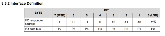
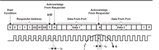
I am using a LaunchXL -F28379D with PCF8574A. For my application, P0-P7 pins are either pulled up or pulled down and I would like to read this as a binary pattern. For example, 0000 1000 would be read as 8.

I understand that the slave address for PCF8574A is 0x38 to 0x3F. In my case I only have a single IO expander on each of my launchpads so I will be using 0x38 (i.e. A0, A1, A2 all grounded).

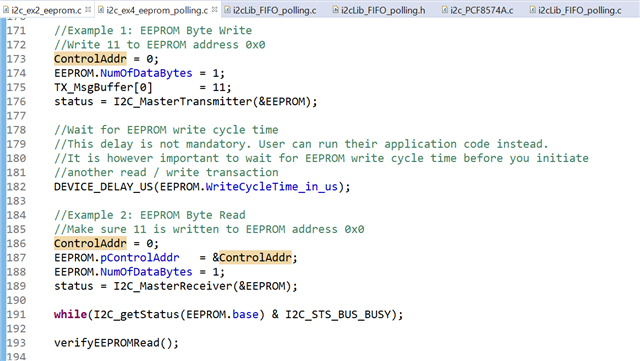
I am trying to use i2c_ex4_eeprom_polling example as a reference for I2C communication as I am not using the interrupt line.

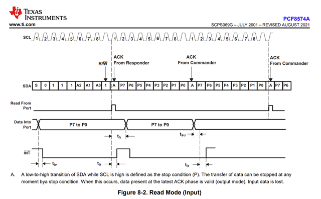
Could you please guide on how to proceed with reading the pins P0-P7? 

Regards,

Rashmitha

  • Hello Rashmitha,

    I'm not sure I understand what you're trying to do. Are you trying to determine whether P0-P7 on the F28379D device have the pull-up enabled? There is a register to control the pull-up disable, but I'm not sure how you would be determining if a pin is configured for pull up or pull down, since this will depend more on the hardware setup if the pull-up disable register isn't being used. Please let me know if I'm not understanding what you're trying to accomplish.

    Best regards,

    Omer Amir

  • Hi ,

    Thanks for your response.

    My application has multiple launchpads and I am using the IO expander to get the physical location (position) of each launchpad. For this purpose, I have pull-up or pull-down resistors soldered permanently (externally; not using the register you mentioned) as per the physical location of the launchpad. 
    For example, the 3rd board will have P0 and P1 pins pulled up and P2 to P7 pulled down. I am referring to P0-P7 on PCF8574A. I would like to read the value of these pins over I2C from F28379D.

    Regards,

    Rashmitha

  • Hello Rashmitha,

    If you're reading these pins as inputs, can you control the state of each pin (i.e. if it's open or closed with regards to the pull up/down circuit)? If so, you could have them all set to be in the open state for the switches and read the incoming value to determine if it's pull up/down. That would be the only way I can think of to determine a pin's is a pull up/down condition. You may need some sort of handshake to get this to happen on the PCF8574A if another device wants to check this. Let me know if this helps.

    Best regards,

    Omer Amir

  • Hi ,

    I am not sure what you mean by open and closed state of each pin for the switches. Could you please elaborate?

    Is there any example project for reading inputs from PCF8574A using F28379D as I2C Master? I am not able to find any programming related document for this chip. Could you please point me to examples or documents that is available for PCF8574A?

    Regards,

    Rashmitha

  • Hello Rashmitha,

    By open state for the pin, I mean the below:

    However you have configured the pins you mentioned, set them all to be in the open state (i.e. physically open switch), and you should be able to tell by the voltage coming in which type of resistor it's using (pull up vs pull down). Are these always going to be in known positions, since you mentioned them being soldered permanently? If so you could just hard code this in your software, there should be no need to read the pin.

    Regarding the PCF8574A, I'm not sure who manages the examples and documentation for this device. For now, you can look at TI's website for the datasheet and other documentation provided there, I'll see if I can find anything else. For using F28379D as an I2C controller, you can look at the examples provided in C2000Ware: C2000Ware_4_XX_XX_XX\driverlib\f2837xd\examples\cpu1\i2c.

    Best regards,

    Omer Amir

  • Hi ,

    If so you could just hard code this in your software, there should be no need to read the pin.

    We want the software to be the same on all the devices in the production stage which is why this IO expander has been introduced in the design so that we can configure/solder the resistors and let them indicate the physical location of each launchpad. The slave launchpads would read their own IO expander chip, read the value configured in it and report their physical location number to a master launchpad.


    For now, you can look at TI's website for the datasheet and other documentation provided there, I'll see if I can find anything else.

    I have been looking at the website for this chip, other than theoretical explanation on the procedure for reading the pins there is no example or programming related help there. 

    For using F28379D as an I2C controller, you can look at the examples provided in C2000Ware: C2000Ware_4_XX_XX_XX\driverlib\f2837xd\examples\cpu1\i2c.

    Thanks for that. I am referring to the I2C examples in C2000Ware. 

    Please do let me know if there is any simple demo project available for reading pins on PCF8574A.

    Regards,

    Rashmitha

  • Hi Rashmitha,

    We do not supply any demo projects / code for the PCF8574A. There is quite a lot of online material using the MSP430 on quite a few TI parts with similar register reads/writes. There is also code on the web using higher level programs like arduino/energia for several I2C devices similar to PCF8574A. 

    Regards,

    Tyler

  • Hi ,

    Thank you for your reply.

    There is quite a lot of online material using the MSP430 on quite a few TI parts with similar register reads/writes.

    Could you help me with the name of devices that are similar to PCF8574A for which MSP430 based help is available?


    I understand that you don't have any demo code available for PCF8574A.

    But I don't even see a document listing the registers, register addresses, a flowchart on steps or guiding on programming of the device.

    The only document I can see on the TI website is the datasheet which does not give a lot of information for a user who is using this chip for the first time.

    Regards,

    Rashmitha

  • Hi Rashmitha,

    Here is a bit of sample code from another customer posted to the online e2e forum some time ago. Link here.

    This person began coding with the MSP430G2553 with PCF8574. Note, there is quite a lot of setup to make I2C work on the MSP430, hence all of the bit sets in the setup function. You will also have to make your own I2C write/read functions, as these are not built in. If you want higher level code that has I2C commands already built in, try using arduino or energia ide's. 

    Here is another link I found with some code here.

    I am not guaranteeing that these coding examples would work, but they are definitely good starts to programming the MSP430 correctly. 

    You could also look for sample code online for the TCA9534 or generally any of the I/O expander family containing the TCAL, TCA, or PCA prefix. Most of the device have similar ways of reading/writing data to the registers. 

    Section 8.4 is from the datasheet of the PCF8574A. This gives you a general idea on how to make a write to the i/o expander. First send the address followed by the data you want to set for each p-port. 

    This device is quite old (from 2001). Our PCA, TCA, and TCAL devices give more in-depth descriptions about register functionality which comes in handy when coding these devices. 

    Please let me know if I can clarify further,

    Regards,

    Tyler

  • Hi ,

    Thank you so much for the elaborate reply.

    I am not guaranteeing that these coding examples would work, but they are definitely good starts to programming the MSP430 correctly. 

    I am not trying to implement with MSP430, I am using F28379D Launchpad. Do you have anything related to C2000 devices?

    Question 1:

    I am referring to I2C example i2c_ex4_eeprom_polling.c from C2000ware. And one of the things that I cannot map is while reading/writing to EEPROM there is a ControlAddr parameter with the address passed. What will this address be if I am trying to access port P0-P7?

    Question 2:

    Is the delay in microseconds (Delay_us) between multiple attempts to check if the bus is busy, is it 4.7 us ? I am looking for the value to be used in below functions

    Question 3:

    At which point in the flow of steps (the list mentioned below) are the data bytes mentioned in this 8.3.2 table sent from PCF8574A to I2C master?

    Question 4:

    Which one of the below should be used to detect an acknowledgement from PCF8574A?

    Below is my understanding of the flow of steps for a read operation ( I am only interested in reading the state of P0-07 (high or low))

    1. Master sends start condition

    2. Master sends slave address with R/W bit(LSB) - 0x 38 & 0x01

    3. Master sends stop condition

    4. Slave sends acknowledgement

    5. Slave sends data P0-P7

    I am not using the INT line, it is just pulled up and not connected to the launchpad.

    Please suggest if I am missing any steps.

    Regards, 

    Rashmitha

  • Hi Rashmitha,

    I will try to get back to you by the end of the day today (CST time).

    Regards,

    Tyler

  • Rashmitha,

    I am not trying to implement with MSP430, I am using F28379D Launchpad. Do you have anything related to C2000 devices?

    We do not have code related to the C2000 available from our team. 

    Question 1:

    I am referring to I2C example i2c_ex4_eeprom_polling.c from C2000ware. And one of the things that I cannot map is while reading/writing to EEPROM there is a ControlAddr parameter with the address passed. What will this address be if I am trying to access port P0-P7?

    First send a start condition which is initiated by the controller device. Then send the device address byte + read/write bit according to the table definition in section 8.3.2 of the datasheet:

    If R/W bit is HIGH, data from the device are the values read from the P-ports.

    If R/W bit is LOW, data from the controller will output to the P-ports

    Question 2:

    Is the delay in microseconds (Delay_us) between multiple attempts to check if the bus is busy, is it 4.7 us ? I am looking for the value to be used in below functions

    Tbuf is the bus free time between a STOP and START condition based off I2C timing standards. The time between the STOP and START bit is minimum of 4.7us.

    Question 3:

    I believe I answer this question in question 2. 

    Please read section 8.3.1 I2C interface section on page 13 of the datasheet.

    Question 4: 

    Which one of the below should be used to detect an acknowledgement from PCF8574A?

    I am not too familiar with C2000ware, but at first glance you could probably use the modules I2C_STS_NO_ACK (No-acknowledgment), or I2C_STS_NACK_SENT (NACK was sent). Based off these status bits, you can determine whether or not an ACK was sent from the PCF8574. 

    I think your step for the stop condition is off.

    Based off page 10 of the datasheet, we can confirm the correct order of I2C transaction.

    1. Controller sends a start condition.

    2. Controller sends target address (PCF8574A address) followed by the R/W bit

    3. Acknowledge is sent by the PCF8574A to the controller

    4. Data is read from the p-port

    5. acknowledge is sent by the PCF8574A to the controller (this is repeated for every repeated read). When communication is finished, assert a STOP condition by controller.

    Please let me know if you have any more questions.

    Regards,

    Tyler

  • Hi ,

    Thanks a lot of the elaborate explanation. I am now able to read the data from the pins.

    However, I am not getting the value of pin P7. Even when the pin is pulled up and can be read as 5V using a multimeter the I2C read is only picking up 0.

    I have tried on multiple ICs, its the same problem across all the ICs that I am using. Is this a known issue?

    I am using I2C at 100kHz and below is my read function. I can detect the device on the I2C network with address 0x38 with I2CBusScan function available in C2000ware library.  

    STATUS_I2C i2cRead(I2CFRAME *msgFrame)
    {
        uint8_t *frame = msgFrame->msgBuffer;
        const int ATTEMPTS = 5000;
        STATUS_I2C status = SUCCESS_RTC;
        I2C_disableFIFO(I2C_PORT);
        I2C_enableFIFO(I2C_PORT);
    
        if (isFuncValid((FuncPtr) I2C_getStopConditionStatus, false, ATTEMPTS))
        {
            //  printf("\nI2C_getStopConditionStatus: i2cMasRead success\n");
            if (isFuncValid((FuncPtr) I2C_isBusBusy, false, ATTEMPTS))
            {
                int buffLoc = 0;
                status = I2C_TransmitSlaveAddressControlBytes(msgFrame);
                I2C_setConfig(I2C_PORT,
                              (I2C_MASTER_RECEIVE_MODE | I2C_REPEAT_MODE));
                I2C_setSlaveAddress(I2C_PORT, msgFrame->slaveAddr);
                I2C_setDataCount(I2C_PORT, msgFrame->numOfBytes);
                I2C_sendStartCondition(I2C_PORT);
                while (!(I2C_getStatus(I2C_PORT) & I2C_STS_REG_ACCESS_RDY))
                    ;
    
                for (int i = 0; i < (msgFrame->numOfBytes) / I2C_FIFO_LEVEL; i++)
                {
                    if (!isFuncValid((FuncPtr) I2C_getRxFIFOStatus, I2C_FIFO_RXFULL,
                                     ATTEMPTS))
                    {
                        //     printf("i2c Rx FAILED %d\n",i);
                        break;
                    }
                    else
                    {
                        for (int i = 0; i < I2C_FIFO_LEVEL; i++)
                        {
                            frame[buffLoc++] = I2C_getData(I2C_PORT);
                            //        printf("Rx i2c Success %d %d\n", buffLoc-1,frame[buffLoc-1]);
                        }
                    }
                }
    
                uint16_t remainingBytes = ((msgFrame->numOfBytes) % I2C_FIFO_LEVEL);
                if (!isFuncValid((FuncPtr) I2C_getRxFIFOStatus, remainingBytes,
                                 ATTEMPTS))
                {
                    //      printf("i2c Rx FAILED @ 2\n");
                }
                I2C_sendStopCondition(I2C_PORT);
                for (int i = 0; i < remainingBytes; i++)
                {
                    frame[buffLoc++] = I2C_getData(I2C_PORT);
                    //    printf("Rx i2c Success-2 %d %d\n", buffLoc-1,frame[buffLoc-1]);
                }
                //    printf("Read done @ %d\n",buffLoc);
                status = handleNACK(I2C_PORT);
                if (status)
                {
                    return status;
                }
                else
                {
                    I2C_disableFIFO(I2C_PORT);
                    if (isFuncValid((FuncPtr) I2C_getStopConditionStatus, false,
                                    ATTEMPTS))
                        ;
                }
            }
            else
            {
                status = ERROR_BUS_BUSY;
            }
        }
        else
        {
            status = ERROR_STOP_NOT_READY;
        }
        //  printf("Completed MasterRead\n");
        return status;
    }

    Could you please check if this issue can be reproduced with any of the chips that you have available? Because we can see this on about 21 chips that we have soldered on our PCBs.

    Below is a screenshot of SCL and SDA lines for a Read operation and the values on the pins are P7-HIGH, P6-LOW, P5-HIGH. But I cannot read P7 as HIGH with the code, other 2 values are read correctly. If you are able to decode the oscilloscope image, P4 and P0 might also be HIGH. That can be ignore, it is because these pins are left floating and have not been pulled down.

    Regards,

    Rashmitha

  • Rashmitha,

    Tyler is out of office until next week. Please allow some time for him to get back to this thread.

    Regards,

    Eric Hackett 

  • Hi ,

    Could you loop in another I2C expert? I am trying to get this resolved asap.

    Regards,

    Rashmitha

  • Rashmitha,

    Did you set/write to the pins to be an output high? Pins that are intended to be inputs with this device are required to be set to high. If any write transactions prior to this did a write low to a port bit then it will always read a low when u do a read transaction. 

    Please also note that the device will only provide the current state of the pin and not any prior changes such as a button press and release. If you read during the button press then u will see that state, if you read after the release you will see the release state. 

    -Bobby