This thread has been locked.

If you have a related question, please click the "Ask a related question" button in the top right corner. The newly created question will be automatically linked to this question.

LAUNCHXL-F280049C: Enable ePWM(3A/B, 4A/B, 5A/B)

Part Number: LAUNCHXL-F280049C
Other Parts Discussed in Thread: C2000WARE

Hello, 

I tried to modify the C2000 built-in example "hrowm_ex1_duty_sfo_v8.c" to also enable EPWM5A by setting GPAPUD.bit.GPIO8 to 1 & setting GPAMUX1.bit.GPIO8=1(changed PWM_CH=3), it does not work, I guess the ePWM5A, GPIO8, is either NOT enable or always-low.

Two uncommon things: GPIO0,GPIO1(ePWM[0], ePWM[1]) are good, while I found the value of ePWM[2]=0??? So, something are wrong here. SWFSYNC=1 in ePWM[2] case, I found online explanation saying that this number should be zero, but I dont know how to fix this. 

  • Hua,

    Is your code based on any example or you wrote it?

    The base address for the EPWM registers are as shown below:

    Can you check where you are assigning the base address of EPWMs in the array?

    Regards, Santosh

  • Santosh,

    bulit-in example: hrowm_ex1_duty_sfo_v8.c.


    I checked multiple sub-code files, stil not sure where it assigns address. the previous picture shown the addresses on the top right corner. Also checked the new zoom-in attachment. What hints can we get from this? 

    please advise!

  • Hi,

    Can you share the project so that I can review it?

    It is very difficult for you me comment otherwise

    Regards, Santosh

  • //#############################################################################

    //

    // FILE:    hrpwm_ex1_duty_sfo_v8.c

    //

    // TITLE:   HRPWM SFO V8 High-Resolution Period

    //          (Up Count) example

    //

    //! \addtogroup bitfield_example_list

    //! <h1>HRPWM Duty Up Count</h1>

    //!

    //! This example modifies the MEP control registers to show edge displacement

    //! for high-resolution period with ePWM in Up count mode

    //! due to the HRPWM control extension of the respective ePWM module.

    //!

    //! This example calls the following TI's MEP Scale Factor Optimizer (SFO)

    //! software library V8 functions:

    //!

    //! \b int \b SFO(); \n

    //! updates MEP_ScaleFactor dynamically when HRPWM is in use

    //! updates HRMSTEP register (exists only in EPwm1Regs register space)

    //! with MEP_ScaleFactor value

    //! - returns 2 if error: MEP_ScaleFactor is greater than maximum value of 255

    //!   (Auto-conversion may not function properly under this condition)

    //! - returns 1 when complete for the specified channel

    //! - returns 0 if not complete for the specified channel

    //!

    //! This example is intended to explain the HRPWM capabilities. The code can be

    //! optimized for code efficiency. Refer to TI's Digital power application

    //! examples and TI Digital Power Supply software libraries for details.

    //!

    //! To run this example:

    //! -# Run this example at maximum SYSCLKOUT

    //! -# Activate Real time mode

    //! -# Run the code

    //!

    //! \b External \b Connections \n

    //!  - Monitor ePWM1 A/B pins on an oscilloscope.

    //!

    //! \b Watch \b Variables \n

    //!  - status - Example run status

    //!  - UpdateFine - Set to 1 use HRPWM capabilities and observe in fine MEP

    //!                 steps(default)

    //!                 Set to 0 to disable HRPWM capabilities and observe in

    //!                 coarse SYSCLKOUT cycle steps

    //!

    //

    //#############################################################################

    //

    //

    // $Copyright:

    // Copyright (C) 2022 Texas Instruments Incorporated - http://www.ti.com/

    //

    // Redistribution and use in source and binary forms, with or without 

    // modification, are permitted provided that the following conditions 

    // are met:

    // 

    //   Redistributions of source code must retain the above copyright 

    //   notice, this list of conditions and the following disclaimer.

    // 

    //   Redistributions in binary form must reproduce the above copyright

    //   notice, this list of conditions and the following disclaimer in the 

    //   documentation and/or other materials provided with the   

    //   distribution.

    // 

    //   Neither the name of Texas Instruments Incorporated nor the names of

    //   its contributors may be used to endorse or promote products derived

    //   from this software without specific prior written permission.

    // 

    // THIS SOFTWARE IS PROVIDED BY THE COPYRIGHT HOLDERS AND CONTRIBUTORS 

    // "AS IS" AND ANY EXPRESS OR IMPLIED WARRANTIES, INCLUDING, BUT NOT 

    // LIMITED TO, THE IMPLIED WARRANTIES OF MERCHANTABILITY AND FITNESS FOR

    // A PARTICULAR PURPOSE ARE DISCLAIMED. IN NO EVENT SHALL THE COPYRIGHT 

    // OWNER OR CONTRIBUTORS BE LIABLE FOR ANY DIRECT, INDIRECT, INCIDENTAL, 

    // SPECIAL, EXEMPLARY, OR CONSEQUENTIAL DAMAGES (INCLUDING, BUT NOT 

    // LIMITED TO, PROCUREMENT OF SUBSTITUTE GOODS OR SERVICES; LOSS OF USE,

    // DATA, OR PROFITS; OR BUSINESS INTERRUPTION) HOWEVER CAUSED AND ON ANY

    // THEORY OF LIABILITY, WHETHER IN CONTRACT, STRICT LIABILITY, OR TORT 

    // (INCLUDING NEGLIGENCE OR OTHERWISE) ARISING IN ANY WAY OUT OF THE USE 

    // OF THIS SOFTWARE, EVEN IF ADVISED OF THE POSSIBILITY OF SUCH DAMAGE.

    // $

    //#############################################################################

    //

    // Included Files

    //

    #include "F28x_Project.h"

    #include "SFO_V8.h"

    //

    // Defines

    //

    #define PWM_CH            3       // # of PWM channels - 1  //change from 2to4.

    #define STATUS_SUCCESS    1

    #define STATUS_FAIL       0

    #define AUTOCONVERT       0       // 1 = Turn auto-conversion ON

                                      // 0 = Turn auto-conversion OFF

    //

    // Globals

    //

    uint16_t UpdateFine;

    uint16_t DutyFine;

    uint16_t status;

    uint16_t CMPA_reg_val;

    uint16_t CMPAHR_reg_val;

    uint16_t CMPB_reg_val;

    uint16_t CMPBHR_reg_val;

    int MEP_ScaleFactor; // Global variable used by the SFO library

                         // Result can be used for all HRPWM channels

                         // This variable is also copied to HRMSTEP

                         // register by SFO() function.

    // Used by SFO library (ePWM[0] is a dummy value that isn't used)

    volatile struct EPWM_REGS *ePWM[PWM_CH] = {&EPwm1Regs, &EPwm1Regs};

    //

    // Function Prototypes

    //

    void initHRPWM1GPIO(void);

    void configHRPWM(uint16_t period);

    void error(void);

    //

    // Main

    //

    void main(void)

    {

        uint16_t i;

        uint32_t temp, temp1;

        //

        // Initialize device clock and peripherals

        //

        InitSysCtrl();

        //

        // Initialize GPIO

        //

        InitGpio();

        initHRPWM1GPIO();

        //

        // Initialize PIE and clear PIE registers. Disables CPU interrupts.

        //

        DINT;

        InitPieCtrl();

        IER = 0x0000;

        IFR = 0x0000;

        //

        // Initialize the PIE vector table with pointers to the shell Interrupt

        // Service Routines (ISR).

        //

        InitPieVectTable();

        //

        // Setup example variables

        //

        UpdateFine = 1;

        DutyFine = 0;

        status = SFO_INCOMPLETE;

        //

        // Enable Global Interrupt (INTM) and realtime interrupt (DBGM)

        //

        EINT;

        ERTM;

        //

        // ePWM and HRPWM register initialization

        //

        for(i=1; i<PWM_CH; i++)

        {

            // Change clock divider to /1

            // (PWM clock needs to be > 60MHz)

            (*ePWM[i]).TBCTL.bit.HSPCLKDIV = 0;

        }

        configHRPWM(10);  


        //

        // Calling SFO() updates the HRMSTEP register with calibrated

        // MEP_ScaleFactor. HRMSTEP must be populated with a scale factor value

        // prior to enabling high resolution period control.

        //

        while(status == SFO_INCOMPLETE)

        {

            status = SFO();

            if(status == SFO_ERROR)

            {

                error();   // SFO function returns 2 if an error occurs & # of MEP

            }              // steps/coarse step exceeds maximum of 255.

        }

        EALLOW;

        for(;;)

        {

            //

            // Sweep DutyFine as a Q15 number from 0.2 - 0.999

            //

            //for(DutyFine = 0x199A; DutyFine < 0x7FDF; DutyFine++)  //origin code

            for(DutyFine = 0x199A; DutyFine < 0x199F; DutyFine++)

            {

                if(UpdateFine)

                {

                    /*

                    // all below calculation apply for CMPB as well

                    // CMPA_reg_val , CMPA_reg_val is calculated as a Q0.

                    // Since DutyFine is a Q15 number, and the period is Q0

                    // the product is Q15. So to store as a Q0, we shift right

                    // 15 bits.

                    CMPA_reg_val = ((long)DutyFine * (EPwm1Regs.TBPRD + 1)) >> 15;

                    // This next step is to obtain the remainder which was

                    // truncated during our 15 bit shift above.

                    // compute the whole value, and then subtract CMPA_reg_val

                    // shifted LEFT 15 bits:

                    temp = ((long)DutyFine * (EPwm1Regs.TBPRD + 1)) ;

                    temp = temp - ((long)CMPA_reg_val<<15);

                    // If auto-conversion is disabled, the following step can be

                    // skipped. If autoconversion is enabled, the SFO function will

                    // write the MEP_ScaleFactor to the HRMSTEP register and the

                    // hardware will automatically scale the remainder in the

                    // CMPAHR register by the MEP_ScaleFactor.

                    // Because the remainder calculated above (temp) is in Q15

                    // format, it must be shifted left by 1 to convert to Q16

                    // format for the hardware to properly convert.

                    CMPAHR_reg_val = temp<<1;

                    // If auto-conversion is enabled, the following step is

                    // performed automatically in hardware and can be skipped

                    // This obtains the MEP count in digits, from

                    // 0,1, .... MEP_Scalefactor.

                    // 0x0080 (0.5 in Q8) is converted to 0.5 in Q15 by shifting

                    // left 7. This is added to fractional duty*MEP_SF product in

                    // order to round the decimal portion of the product up to the

                    // next integer if the decimal portion is >=0.5.

                    //

                    //Once again since this is Q15

                    // convert to Q0 by shifting:

                    CMPAHR_reg_val = (temp*MEP_ScaleFactor+(0x0080<<7))>>15;

                    // If auto-conversion is enabled, the following step is

                    // performed automatically in hardware and can be skipped

                    // Now the lower 8 bits contain the MEP count.

                    // Since the MEP count needs to be in the upper 8 bits of

                    // the 16 bit CMPAHR register, shift left by 8.

                    CMPAHR_reg_val = CMPAHR_reg_val << 8;

                    // If auto-conversion is enabled, the following step is

                    // performed automatically in hardware and can be skipped

                    // Add the offset and rounding

                    CMPAHR_reg_val += 0x0080;

                    // Write the values to the registers as one 32-bit

                    // or two 16-bits

                    EPwm1Regs.CMPA.bit.CMPA = CMPA_reg_val;

                    EPwm1Regs.CMPA.bit.CMPAHR = CMPAHR_reg_val;

                    */

                    //

                    // All the above operations may be condensed into

                    // the following form:

                    // EPWM1 calculations

                    //

                    for(i=1; i<PWM_CH; i++)

                    {

                        CMPA_reg_val = ((long)DutyFine * ((*ePWM[i]).TBPRD + 1)) >> 15;

                        CMPB_reg_val = ((long)DutyFine * ((*ePWM[i]).TBPRD + 1)) >> 15;

                        temp = ((long)DutyFine * ((*ePWM[i]).TBPRD + 1)) ;

                        temp1 = ((long)DutyFine * ((*ePWM[i]).TBPRD + 1)) ;

                        temp = temp - ((long)CMPA_reg_val << 15);

                        temp1 = temp1 - ((long)CMPB_reg_val << 15);

                       #if(AUTOCONVERT)

                        CMPAHR_reg_val = temp << 1; // convert to Q16

                        CMPBHR_reg_val = temp << 1; // convert to Q16

                       #else

                        CMPAHR_reg_val = ((temp * MEP_ScaleFactor) +

                                          (0x0080 << 7)) >> 15;

                        CMPAHR_reg_val = CMPAHR_reg_val << 8;

                        CMPBHR_reg_val = ((temp1 * MEP_ScaleFactor) +

                                          (0x0080 << 7)) >> 15;

                        CMPBHR_reg_val = CMPBHR_reg_val << 8;

                       #endif

                       //

                       // Example for a 32 bit write to CMPA:CMPAHR

                       //

                        (*ePWM[i]).CMPA.all = ((long)CMPA_reg_val) << 16 |

                                              CMPAHR_reg_val; // loses lower 8-bits

                       //

                       // Example for a 32 bit write to CMPB:CMPBHR

                       //

                        (*ePWM[i]).CMPB.all = ((long)CMPB_reg_val) << 16 |

                                              CMPBHR_reg_val; // loses lower 8-bits

                    }

                }

                else

                {

                    //

                    // CMPA_reg_val is calculated as a Q0.

                    // Since DutyFine is a Q15 number, and the period is Q0

                    // the product is Q15. So to store as a Q0, we shift right

                    // 15 bits.

                    //

                    for(i=1; i<PWM_CH; i++)

                    {

                        (*ePWM[i]).CMPA.bit.CMPA = (((long)DutyFine *

                                                    ((*ePWM[i]).TBPRD + 1)) >> 15);

                        (*ePWM[i]).CMPB.bit.CMPB = (((long)DutyFine *

                                                    ((*ePWM[i]).TBPRD + 1)) >> 15);

                    }

                }

                //

                // Call the scale factor optimizer lib function SFO()

                // periodically to track for any change due to temp/voltage.

                // This function generates MEP_ScaleFactor by running the

                // MEP calibration module in the HRPWM logic. This scale

                // factor can be used for all HRPWM channels. The SFO()

                // function also updates the HRMSTEP register with the

                // scale factor value.

                //

                status = SFO(); // in background, MEP calibration module

                                // continuously updates MEP_ScaleFactor

                if (status == SFO_ERROR)

                {

                    error();   // SFO function returns 2 if an error occurs & #

                               // of MEP steps/coarse step exceeds maximum of 255.

                }

            } // end DutyFine for loop

        } // end infinite for loop

    }

    //

    // configHRPWM - Configures all ePWM channels and sets up HRPWM

    //                on ePWMxA / ePWMxB  channels

    //

    void configHRPWM(uint16_t period)

    {

        uint16_t j;

        for (j=1;j<PWM_CH;j++)

        {

            (*ePWM[j]).TBCTL.bit.PRDLD = TB_SHADOW;  // set Immediate load

            (*ePWM[j]).TBPRD = 10*(period-1);             // PWM frequency = 1 / period   ///scale up 10times [12/12/22]

            (*ePWM[j]).CMPA.bit.CMPA = 10*(period / 2);   // set duty 50% initially  ///factor of 10 concerns

            (*ePWM[j]).CMPA.bit.CMPAHR = (1 << 8);   // initialize HRPWM extension

            (*ePWM[j]).CMPB.bit.CMPB = 10*(period / 2);   // set duty 50% initially

            (*ePWM[j]).CMPB.all |= (1 << 8);         // initialize HRPWM extension

            (*ePWM[j]).TBPHS.all = 0;

            (*ePWM[j]).TBCTR = 0;

            (*ePWM[j]).TBCTL.bit.CTRMODE = TB_COUNT_UP;

            (*ePWM[j]).TBCTL.bit.PHSEN = TB_DISABLE;

            (*ePWM[j]).TBCTL.bit.SYNCOSEL = TB_SYNC_DISABLE;

            (*ePWM[j]).TBCTL.bit.HSPCLKDIV = TB_DIV1;

            (*ePWM[j]).TBCTL.bit.CLKDIV = TB_DIV1;

            (*ePWM[j]).TBCTL.bit.FREE_SOFT = 11;

            (*ePWM[j]).CMPCTL.bit.LOADAMODE = CC_CTR_ZERO;

            (*ePWM[j]).CMPCTL.bit.LOADBMODE = CC_CTR_ZERO;

            (*ePWM[j]).CMPCTL.bit.SHDWAMODE = CC_SHADOW;

            (*ePWM[j]).CMPCTL.bit.SHDWBMODE = CC_SHADOW;

            (*ePWM[j]).AQCTLA.bit.ZRO = AQ_SET;      // PWM toggle high/low

            (*ePWM[j]).AQCTLA.bit.CAU = AQ_CLEAR;

            (*ePWM[j]).AQCTLB.bit.ZRO = AQ_SET;

            (*ePWM[j]).AQCTLB.bit.CBU = AQ_CLEAR;

            EALLOW;

            (*ePWM[j]).HRCNFG.all = 0x0;

            (*ePWM[j]).HRCNFG.bit.EDGMODE = HR_FEP;  // MEP control on falling edge

            (*ePWM[j]).HRCNFG.bit.CTLMODE = HR_CMP;

            (*ePWM[j]).HRCNFG.bit.HRLOAD  = HR_CTR_ZERO;

            (*ePWM[j]).HRCNFG.bit.EDGMODEB = HR_FEP; // MEP control on falling edge

            (*ePWM[j]).HRCNFG.bit.CTLMODEB = HR_CMP;

            (*ePWM[j]).HRCNFG.bit.HRLOADB  = HR_CTR_ZERO;

            #if (AUTOCONVERT)

            (*ePWM[j]).HRCNFG.bit.AUTOCONV = 1;     // Enable auto-conversion

                                                    // logic

            #endif

            (*ePWM[j]).HRPCTL.bit.HRPE = 0; // Turn off high-resolution period

                                            // control.

            EDIS;

        }

    }

    //

    // initHRPWM1GPIO - Initialize HRPWM1 GPIOs

    //

    void initHRPWM1GPIO(void)

    {

        EALLOW;

        //

        // Disable internal pull-up for the selected output pins

        // for reduced power consumption

        // Pull-ups can be enabled or disabled by the user.

        //

        GpioCtrlRegs.GPAPUD.bit.GPIO0 = 1;    // Disable pull-up on GPIO0 (EPWM1A)

        GpioCtrlRegs.GPAPUD.bit.GPIO1 = 1;    // Disable pull-up on GPIO1 (EPWM1B)

        GpioCtrlRegs.GPAPUD.bit.GPIO8 = 1;    // Disable pull-up on GPIO1 (EPWM5A)   //12/12/22

        //

        // Configure EPWM-1 pins using GPIO regs

        // This specifies which of the possible GPIO pins will be EPWM1 functional

        // pins.

        //

        GpioCtrlRegs.GPAMUX1.bit.GPIO0 = 1;   // Configure GPIO0 as EPWM1A

        GpioCtrlRegs.GPAMUX1.bit.GPIO1 = 1;   // Configure GPIO1 as EPWM1B

        GpioCtrlRegs.GPAMUX1.bit.GPIO8 = 1;   // Configure GPIO0 as EPWM5A

        EDIS;

    }

    //

    // error - Halt debugger when called

    //

    void error(void)

    {

        ESTOP0;         // Stop here and handle error

    }

    //

    // End of file

    //

    2nd2nd

    2nd2nd

    2nd2nd

    2nd2nd

    2nd2nd

    gpio_c code:

    //###########################################################################

    //

    // FILE:   f28004x_gpio.c

    //

    // TITLE:  f28004x GPIO module support functions

    //

    //###########################################################################

    //

    //

    // $Copyright:

    // Copyright (C) 2022 Texas Instruments Incorporated - http://www.ti.com/

    //

    // Redistribution and use in source and binary forms, with or without 

    // modification, are permitted provided that the following conditions 

    // are met:

    // 

    //   Redistributions of source code must retain the above copyright 

    //   notice, this list of conditions and the following disclaimer.

    // 

    //   Redistributions in binary form must reproduce the above copyright

    //   notice, this list of conditions and the following disclaimer in the 

    //   documentation and/or other materials provided with the   

    //   distribution.

    // 

    //   Neither the name of Texas Instruments Incorporated nor the names of

    //   its contributors may be used to endorse or promote products derived

    //   from this software without specific prior written permission.

    // 

    // THIS SOFTWARE IS PROVIDED BY THE COPYRIGHT HOLDERS AND CONTRIBUTORS 

    // "AS IS" AND ANY EXPRESS OR IMPLIED WARRANTIES, INCLUDING, BUT NOT 

    // LIMITED TO, THE IMPLIED WARRANTIES OF MERCHANTABILITY AND FITNESS FOR

    // A PARTICULAR PURPOSE ARE DISCLAIMED. IN NO EVENT SHALL THE COPYRIGHT 

    // OWNER OR CONTRIBUTORS BE LIABLE FOR ANY DIRECT, INDIRECT, INCIDENTAL, 

    // SPECIAL, EXEMPLARY, OR CONSEQUENTIAL DAMAGES (INCLUDING, BUT NOT 

    // LIMITED TO, PROCUREMENT OF SUBSTITUTE GOODS OR SERVICES; LOSS OF USE,

    // DATA, OR PROFITS; OR BUSINESS INTERRUPTION) HOWEVER CAUSED AND ON ANY

    // THEORY OF LIABILITY, WHETHER IN CONTRACT, STRICT LIABILITY, OR TORT 

    // (INCLUDING NEGLIGENCE OR OTHERWISE) ARISING IN ANY WAY OUT OF THE USE 

    // OF THIS SOFTWARE, EVEN IF ADVISED OF THE POSSIBILITY OF SUCH DAMAGE.

    // $

    //###########################################################################

    //

    // Included Files

    //

    #include "f28004x_device.h"

    #include "f28004x_examples.h"

    //

    // Low-level functions for GPIO configuration

    //

    //

    // InitGpio - Sets all pins to be muxed to GPIO in input mode with pull-ups

    // enabled.Also resets CPU control to CPU1 and disables open drain

    // and polarity inversion and sets the qualification to synchronous.

    // Also unlocks all GPIOs. Only one CPU should call this function.

    //

    void

    InitGpio()

    {

        volatile Uint32 *gpioBaseAddr;

        Uint16 regOffset;

        //

        // Disable pin locks

        //

        EALLOW;

        GpioCtrlRegs.GPALOCK.all = 0x00000000;

        GpioCtrlRegs.GPBLOCK.all = 0x00000000;

        GpioCtrlRegs.GPHLOCK.all = 0x00000000;

        //

        // Fill all registers with zeros. Writing to each register separately

        // for three GPIO modules would make this function *very* long.

        // Fortunately, we'd be writing them all with zeros anyway,

        // so this saves a lot of space.

        //

        gpioBaseAddr = (Uint32 *)&GpioCtrlRegs;

        for (regOffset = 0; regOffset < sizeof(GpioCtrlRegs)/2; regOffset++)

        {

            //

            // Must avoid enabling pull-ups on all pins. GPyPUD is offset

            // 0x0C in each register group of 0x40 words. Since this is a

            // 32-bit pointer, the addresses must be divided by 2.

            //

            // Also, to avoid changing pin muxing of the emulator pins to regular

            // GPIOs, skip GPBMUX1 (0x46) and GPBGMUX1 (0x60).

            //

            if ((regOffset % (0x40/2) != (0x0C/2)) && (regOffset != (0x46/2)) &&

                (regOffset != (0x60/2)))

            {

                gpioBaseAddr[regOffset] = 0x00000000;

            }

        }

        gpioBaseAddr = (Uint32 *)&GpioDataRegs;

        for (regOffset = 0; regOffset < sizeof(GpioDataRegs)/2; regOffset++)

        {

            gpioBaseAddr[regOffset] = 0x00000000;

        }

        EDIS;

    }

    //

    // GPIO_SetupPinMux - Set the peripheral muxing for the specified pin.

    // The appropriate parameters can be found in the pinout spreadsheet.

    //

    void

    GPIO_SetupPinMux(Uint16 gpioNumber, Uint16 cpu, Uint16 muxPosition)

    {

        volatile Uint32 *gpioBaseAddr;

        volatile Uint32 *mux, *gmux, *csel;

        Uint16 pin32, pin16, pin8;

        pin32 = gpioNumber % 32;

        pin16 = gpioNumber % 16;

        pin8 = gpioNumber % 8;

        gpioBaseAddr = (Uint32 *)&GpioCtrlRegs + (gpioNumber/32)*GPY_CTRL_OFFSET;

        //

        // Sanity check for valid cpu and peripheral values

        //

        if (cpu > GPIO_MUX_CPU1CLA || muxPosition > 0xF)

        {

            return;

        }

        //

        // Create pointers to the appropriate registers. This is a workaround

        // for the way GPIO registers are defined. The standard definition

        // in the header file makes it very easy to do named accesses of one

        // register or bit, but hard to do arbitrary numerical accesses. It's

        // easier to have an array of GPIO modules with identical registers,

        // including arrays for multi-register groups like GPyCSEL1-4. But

        // the header file doesn't define anything we can turn into an array,

        // so manual pointer arithmetic is used instead.

        //

        mux = gpioBaseAddr + GPYMUX + pin32/16;

        gmux = gpioBaseAddr + GPYGMUX + pin32/16;

        csel = gpioBaseAddr + GPYCSEL + pin32/8;

        //

        // Now for the actual function

        //

        EALLOW;

        //

        // To change the muxing, set the peripheral mux to 0/GPIO first to avoid

        // glitches, then change the group mux, then set the peripheral mux to

        // its target value. Finally, set the CPU select. This procedure is

        // described in the TRM. Unfortunately, since we don't know the pin in

        // advance we can't hardcode a bitfield reference, so there's some tricky

        // bit twiddling here.

        //

        *mux &= ~(0x3UL << (2*pin16));

        *gmux &= ~(0x3UL << (2*pin16));

        *gmux |= (Uint32)((muxPosition >> 2) & 0x3UL) << (2*pin16);

        *mux |= (Uint32)(muxPosition & 0x3UL) << (2*pin16);

        *csel &= ~(0x3L << (4*pin8));

        *csel |= (Uint32)(cpu & 0x3L) << (4*pin8);

        //

        // WARNING: This code does not touch the analog mode select registers.

        //

        EDIS;

    }

    //

    // GPIO_SetupPinOptions - Setup up the GPIO input/output options for the

    // specified pin. The flags are a 16-bit mask produced by ORing together

    // options. For input pins, the valid flags are:

    // GPIO_PULLUP  Enable pull-up

    // GPIO_INVERT  Enable input polarity inversion

    // GPIO_SYNC  Synchronize the input latch to PLLSYSCLK

    //              (default -- you don't need to specify this)

    // GPIO_QUAL3  Use 3-sample qualification

    // GPIO_QUAL6  Use 6-sample qualification

    // GPIO_ASYNC  Do not use synchronization or qualification

    // (Note: only one of SYNC, QUAL3, QUAL6, or ASYNC is allowed)

    //

    // For output pins, the valid flags are:

    // GPIO_OPENDRAIN  Output in open drain mode

    // GPIO_PULLUP    If open drain enabled, also enable the pull-up

    // and the input qualification flags (SYNC/QUAL3/QUAL6/SYNC) listed above.

    //

    // With no flags, the default input state is synchronous with no

    // pull-up or polarity inversion. The default output state is

    // the standard digital output.

    //

    void

    GPIO_SetupPinOptions(Uint16 gpioNumber, Uint16 output, Uint16 flags)

    {

        volatile Uint32 *gpioBaseAddr;

        volatile Uint32 *dir, *pud, *inv, *odr, *qsel;

        Uint32 pin32, pin16, pinMask, qual;

        pin32 = gpioNumber % 32;

        pin16 = gpioNumber % 16;

        pinMask = 1UL << pin32;

        gpioBaseAddr = (Uint32 *)&GpioCtrlRegs + (gpioNumber/32)*GPY_CTRL_OFFSET;

        //

        // Create pointers to the appropriate registers. This is a workaround

        // for the way GPIO registers are defined. The standard definition

        // in the header file makes it very easy to do named accesses of one

        // register or bit, but hard to do arbitrary numerical accesses. It's

        // easier to have an array of GPIO modules with identical registers,

        // including arrays for multi-register groups like GPyQSEL1-2. But

        // the header file doesn't define anything we can turn into an array,

        // so manual pointer arithmetic is used instead.

        //

        dir = gpioBaseAddr + GPYDIR;

        pud = gpioBaseAddr + GPYPUD;

        inv = gpioBaseAddr + GPYINV;

        odr = gpioBaseAddr + GPYODR;

        qsel = gpioBaseAddr + GPYQSEL + pin32/16;

        EALLOW;

        //

        // Set the data direction

        //

        *dir &= ~pinMask;

        if (output == 1)

        {

            //

            // Output, with optional open drain mode and pull-up

            //

            *dir |= pinMask;

            //

            // Enable open drain if necessary

            //

            if (flags & GPIO_OPENDRAIN)

            {

                *odr |= pinMask;

            }

            else

            {

                *odr &= ~pinMask;

            }

            //

            // Enable pull-up if necessary. Open drain mode must be active.

            //

            if (flags & (GPIO_OPENDRAIN | GPIO_PULLUP))

            {

                *pud &= ~pinMask;

            }

            else

            {

                *pud |= pinMask;

            }

        }

        else

        {

            //

            // Input, with optional pull-up, qualification, and polarity inversion

            //

            *dir &= ~pinMask;

            //

            // Enable pull-up if necessary

            //

            if (flags & GPIO_PULLUP)

            {

                *pud &= ~pinMask;

            }

            else

            {

                *pud |= pinMask;

            }

            //

            // Invert polarity if necessary

            //

            if (flags & GPIO_INVERT)

            {

                *inv |= pinMask;

            }

            else

            {

                *inv &= ~pinMask;

            }

        }

        //

        // Extract the qualification parameter and load it into the register.

        // This is also needed for open drain outputs, so we might as well do it

        // all the time.

        //

        qual = (flags & GPIO_ASYNC) / GPIO_QUAL3;

        *qsel &= ~(0x3L << (2 * pin16));

        if (qual != 0x0)

        {

            *qsel |= qual << (2 * pin16);

        }

        EDIS;

    }

    //

    // GPIO_SetupLock - Enable or disable the GPIO register bit lock for the

    // specified pin. The valid flags are:

    // GPIO_UNLOCK  Unlock the pin setup register bits for the specified pin

    // GPIO_LOCK   Lock the pin setup register bits for the specified pin

    //

    void

    GPIO_SetupLock(Uint16 gpioNumber, Uint16 flags)

    {

        volatile Uint32 *gpioBaseAddr;

        volatile Uint32 *lock;

        Uint32 pin32, pinMask;

        pin32 = gpioNumber % 32;

        pinMask = 1UL << pin32;

        gpioBaseAddr = (Uint32 *)&GpioCtrlRegs + (gpioNumber/32)*GPY_CTRL_OFFSET;

        //

        // Create pointers to the appropriate registers. This is a workaround

        // for the way GPIO registers are defined. The standard definition

        // in the header file makes it very easy to do named accesses of one

        // register or bit, but hard to do arbitrary numerical accesses. It's

        // easier to have an array of GPIO modules with identical registers,

        // including arrays for multi-register groups like GPyQSEL1-2. But

        // the header file doesn't define anything we can turn into an array,

        // so manual pointer arithmetic is used instead.

        //

        lock = gpioBaseAddr + GPYLOCK;

        EALLOW;

        if(flags)

        {

            //

            // Lock the pin

            //

            *lock |= pinMask;

        }

        else

        {

            //

            // Unlock the pin

            //

            *lock &= ~pinMask;

        }

        EDIS;

    }

    //

    // External interrupt setup

    //

    void

    GPIO_SetupXINT1Gpio(Uint16 gpioNumber)

    {

        EALLOW;

        InputXbarRegs.INPUT4SELECT = gpioNumber;       // Set XINT1 source to GPIO-pin

        EDIS;

    }

    void

    GPIO_SetupXINT2Gpio(Uint16 gpioNumber)

    {

        EALLOW;

        InputXbarRegs.INPUT5SELECT = gpioNumber;       // Set XINT2 source to GPIO-pin

        EDIS;

    }

    void

    GPIO_SetupXINT3Gpio(Uint16 gpioNumber)

    {

        EALLOW;

        InputXbarRegs.INPUT6SELECT = gpioNumber;       // Set XINT3 source to GPIO-pin

        EDIS;

    }

    void

    GPIO_SetupXINT4Gpio(Uint16 gpioNumber)

    {

        EALLOW;

        InputXbarRegs.INPUT13SELECT = gpioNumber;      // Set XINT4 source to GPIO-pin

        EDIS;

    }

    void

    GPIO_SetupXINT5Gpio(Uint16 gpioNumber)

    {

        EALLOW;

        InputXbarRegs.INPUT14SELECT = gpioNumber;     // Set XINT5 source to GPIO-pin

        EDIS;

    }

    //

    // GPIO_ReadPin - Read the GPyDAT register bit for the specified pin.

    // Note that this returns the actual state of the pin, not the state of the

    // output latch.

    //

    Uint16

    GPIO_ReadPin(Uint16 gpioNumber)

    {

        volatile Uint32 *gpioDataReg;

        Uint16 pinVal;

        gpioDataReg = (volatile Uint32 *)&GpioDataRegs + (gpioNumber/32)*GPY_DATA_OFFSET;

        pinVal = (gpioDataReg[GPYDAT] >> (gpioNumber % 32)) & 0x1;

        return pinVal;

    }

    //

    // GPIO_WritePin - Set the GPyDAT register bit for the specified pin.

    //

    void

    GPIO_WritePin(Uint16 gpioNumber, Uint16 outVal)

    {

        volatile Uint32 *gpioDataReg;

        Uint32 pinMask;

        gpioDataReg = (volatile Uint32 *)&GpioDataRegs + (gpioNumber/32)*GPY_DATA_OFFSET;

        pinMask = 1UL << (gpioNumber % 32);

        if (outVal == 0)

        {

            gpioDataReg[GPYCLEAR] = pinMask;

        }

        else

        {

            gpioDataReg[GPYSET] = pinMask;

        }

    }

    //

    // End of File

    //

    Let me know if you need other code files.

  • volatile struct EPWM_REGS *ePWM[PWM_CH] = {&EPwm1Regs, &EPwm1Regs};

    Looks like you are not assigning the registers correctly in the array.

    Is this your custom application or you are using an example from C2000Ware SDK and you modified it?

    Regards, Santosh

  • I’m using an example from C2000Ware SDK and trying to assign ePWM 3ab, 4ab, 5ab.

    How should I assign the address correctly?

  • Which example did you use?

    I just opened on my system, it is initialized like below.

    volatile uint32_t ePWM[] =

        {0, myEPWM1_BASE, myEPWM2_BASE, myEPWM3_BASE, myEPWM4_BASE};

    Please change accordingly for your application.

  • Jha,

    Thanks! I got the ideas. 

    between the line 351/352/353, we assigned CMPA.bit.CMPA=period/2, CMPB.bit.CMPB=period/2. are we using these variables to determine the dutycycle of PWM? I'm not sure if we are using this in the same code program? or are we using at one other different code?

    At line 375, EALLOW? where is this variable coming from? where is it assigned at first place? 

  • Please try the example from here:

    C:/ti/c2000/C2000Ware_4_02_00_00/driverlib/f28004x/examples/hrpwm/hrpwm_ex1_duty_sfo.c

  • I found it, what is different between using the code from (different folder)C:/ti/c2000/C2000Ware_4_02_00_00/driverlib/f28004x/examples/hrpwm/hrpwm_ex1_duty_sfo.c

    vs

    C:/ti/c2000/C2000Ware_4_02_00_00/devicesupport/f28004x/examples/hrpwm/hrpwm_ex1_duty_sfo.c.


    And, I still cannot find the origin source code for the link 375(above) EALLOW command.  

  • Hi,

    it is a macro in the driverlib cpu.h.

    #ifndef EALLOW

    #ifndef __TMS320C28XX_CLA__

    #define EALLOW __eallow()

    #else

    #define EALLOW __meallow()

    #endif // __TMS320C28XX_CLA__

    #endif // EALLOW

    Looks like you have modified the path, otherwise you should not see this error.

    please try to import any C2000Ware driverLib example, and then it should be there. Rebuild it, and open sysctrl.h, it should be calling EALLOW multiple times.

    Regards, Santosh

  • Hello Santosh,

    Is this C:/ti/c2000/C2000Ware_4_02_00_00/driverlib/f28004x/examples/hrpwm/hrpwm_ex1_duty_sfo.c a upcount PWM output generators?

    does the HRPWM_COUNTER_COMPARE_A and ......COMPARE_B set the upcount points for HRPWMxA and HRPWMxB outputs?

    I saw this code file has initialize GPIO through Device_initGPIO(); (LINE 120), but how do we know which GPIO outputs? are they ePWM1A/1B or ePWM2A/2B?

    If I need a complementary PWM output pairs? (same frequency, same duty ratio, with 180 degree phase shift, can I use this program? what should I modify ?

    Attached the program code below and Best Regards,

    ------------------------------------------------

    //#############################################################################

    //

    // FILE:   hrpwm_ex1_duty_sfo.c

    //

    // TITLE:  HRPWM Duty Control with SFO.

    //

    //! \addtogroup driver_example_list

    //! <h1>HRPWM Duty Control with SFO</h1>

    //!

    //! This example modifies the MEP control registers to show edge displacement

    //! for high-resolution period with ePWM in Up count mode

    //! due to the HRPWM control extension of the respective ePWM module.

    //!

    //! This example calls the following TI's MEP Scale Factor Optimizer (SFO)

    //! software library V8 functions:

    //!

    //! \b int \b SFO(); \n

    //! - updates MEP_ScaleFactor dynamically when HRPWM is in use

    //! - updates HRMSTEP register (exists only in EPwm1Regs register space)

    //! with MEP_ScaleFactor value

    //! - returns 2 if error: MEP_ScaleFactor is greater than maximum value of 255

    //!   (Auto-conversion may not function properly under this condition)

    //! - returns 1 when complete for the specified channel

    //! - returns 0 if not complete for the specified channel

    //!

    //! This example is intended to explain the HRPWM capabilities. The code can be

    //! optimized for code efficiency. Refer to TI's Digital power application

    //! examples and TI Digital Power Supply software libraries for details.

    //!

    //! \b External \b Connections \n

    //!  - Monitor ePWM1/2/3/4 A/B pins on an oscilloscope.

    //

    //#############################################################################

    //

    //

    // $Copyright:

    // Copyright (C) 2022 Texas Instruments Incorporated - http://www.ti.com/

    //

    // Redistribution and use in source and binary forms, with or without 

    // modification, are permitted provided that the following conditions 

    // are met:

    // 

    //   Redistributions of source code must retain the above copyright 

    //   notice, this list of conditions and the following disclaimer.

    // 

    //   Redistributions in binary form must reproduce the above copyright

    //   notice, this list of conditions and the following disclaimer in the 

    //   documentation and/or other materials provided with the   

    //   distribution.

    // 

    //   Neither the name of Texas Instruments Incorporated nor the names of

    //   its contributors may be used to endorse or promote products derived

    //   from this software without specific prior written permission.

    // 

    // THIS SOFTWARE IS PROVIDED BY THE COPYRIGHT HOLDERS AND CONTRIBUTORS 

    // "AS IS" AND ANY EXPRESS OR IMPLIED WARRANTIES, INCLUDING, BUT NOT 

    // LIMITED TO, THE IMPLIED WARRANTIES OF MERCHANTABILITY AND FITNESS FOR

    // A PARTICULAR PURPOSE ARE DISCLAIMED. IN NO EVENT SHALL THE COPYRIGHT 

    // OWNER OR CONTRIBUTORS BE LIABLE FOR ANY DIRECT, INDIRECT, INCIDENTAL, 

    // SPECIAL, EXEMPLARY, OR CONSEQUENTIAL DAMAGES (INCLUDING, BUT NOT 

    // LIMITED TO, PROCUREMENT OF SUBSTITUTE GOODS OR SERVICES; LOSS OF USE,

    // DATA, OR PROFITS; OR BUSINESS INTERRUPTION) HOWEVER CAUSED AND ON ANY

    // THEORY OF LIABILITY, WHETHER IN CONTRACT, STRICT LIABILITY, OR TORT 

    // (INCLUDING NEGLIGENCE OR OTHERWISE) ARISING IN ANY WAY OUT OF THE USE 

    // OF THIS SOFTWARE, EVEN IF ADVISED OF THE POSSIBILITY OF SUCH DAMAGE.

    // $

    //#############################################################################

    //

    // Included Files

    //

    #include "board.h"

    #include "SFO_V8.h"

    #define EPWM_TIMER_TBPRD            100UL

    #define MIN_HRPWM_DUTY_PERCENT      4.0/((float32_t)EPWM_TIMER_TBPRD)*100.0

    //

    // Defines

    //

    #define LAST_EPWM_INDEX_FOR_EXAMPLE    5

    //

    // Globals

    //

    float32_t dutyFine = MIN_HRPWM_DUTY_PERCENT;

    uint16_t status;

    int MEP_ScaleFactor; // Global variable used by the SFO library

                         // Result can be used for all HRPWM channels

                         // This variable is also copied to HRMSTEP

                         // register by SFO() function.

    volatile uint32_t ePWM[] =

        {0, myEPWM1_BASE, myEPWM2_BASE, myEPWM3_BASE, myEPWM4_BASE};

    //

    // Function Prototypes

    //

    void error(void);

    //__interrupt void epwm1ISR(void);

    //__interrupt void epwm2ISR(void);

    //__interrupt void epwm3ISR(void);

    //__interrupt void epwm4ISR(void);

    //

    // Main

    //

    void main(void)

    {

        uint16_t i = 0;

        //

        // Initialize device clock and peripherals

        //

        Device_init();

        //

        // Disable pin locks and enable internal pull ups.

        //

        Device_initGPIO();

        //

        // Initialize PIE and clear PIE registers. Disables CPU interrupts.

        //

        Interrupt_initModule();

        //

        // Initialize the PIE vector table with pointers to the shell Interrupt

        // Service Routines (ISR).

        //

        Interrupt_initVectorTable();

        //

        // Assign the interrupt service routines to ePWM interrupts

        //

        //Interrupt_register(INT_EPWM1, &epwm1ISR);

        //Interrupt_register(INT_EPWM2, &epwm2ISR);

        //Interrupt_register(INT_EPWM3, &epwm3ISR);

        //Interrupt_register(INT_EPWM4, &epwm4ISR);

        //

        // Calling SFO() updates the HRMSTEP register with calibrated MEP_ScaleFactor.

        // HRMSTEP must be populated with a scale factor value prior to enabling

        // high resolution period control.

        //

        while(status == SFO_INCOMPLETE)

        {

            status = SFO();

            if(status == SFO_ERROR)

            {

                error();   // SFO function returns 2 if an error occurs & # of MEP

            }              // steps/coarse step exceeds maximum of 255.

        }

        //

        // Disable sync(Freeze clock to PWM as well)

        //

        SysCtl_disablePeripheral(SYSCTL_PERIPH_CLK_TBCLKSYNC);

        //

        // Initialize the EPWM GPIO Pins and change the XBAR inputs from using GPIO0

        //

        Board_init();

        //

        // Enable sync and clock to PWM

        //

        SysCtl_enablePeripheral(SYSCTL_PERIPH_CLK_TBCLKSYNC);

        // Enable ePWM interrupts

        //

        //Interrupt_enable(INT_EPWM1);

        //Interrupt_enable(INT_EPWM2);

        //Interrupt_enable(INT_EPWM3);

        //Interrupt_enable(INT_EPWM4);

        //

        // Enable Global Interrupt (INTM) and realtime interrupt (DBGM)

        //

        EINT;

        ERTM;

        for(;;)

        {

             //

             // Sweep DutyFine

             //

             for(dutyFine = MIN_HRPWM_DUTY_PERCENT; dutyFine < 99.9; dutyFine += 0.01)

             {

                 DEVICE_DELAY_US(1000);

                 for(i=1; i<LAST_EPWM_INDEX_FOR_EXAMPLE; i++)

                 {

                     float32_t count = (dutyFine * (float32_t)(EPWM_TIMER_TBPRD << 8))/100;

                     uint32_t compCount = (count);

                     HRPWM_setCounterCompareValue(ePWM[i], HRPWM_COUNTER_COMPARE_A, compCount);

                     HRPWM_setCounterCompareValue(ePWM[i], HRPWM_COUNTER_COMPARE_B, compCount);

                 }

                 //

                 // Call the scale factor optimizer lib function SFO()

                 // periodically to track for any change due to temp/voltage.

                 // This function generates MEP_ScaleFactor by running the

                 // MEP calibration module in the HRPWM logic. This scale

                 // factor can be used for all HRPWM channels. The SFO()

                 // function also updates the HRMSTEP register with the

                 // scale factor value.

                 //

                 status = SFO(); // in background, MEP calibration module

                                 // continuously updates MEP_ScaleFactor

                 if (status == SFO_ERROR)

                 {

                     error();   // SFO function returns 2 if an error occurs & #

                                // of MEP steps/coarse step

                 }              // exceeds maximum of 255.

             }

         }

    }

    //

    // epwm1ISR - ePWM 1 ISR

    //

    //__interrupt void epwm1ISR(void)

    //{

    //    EPWM_clearEventTriggerInterruptFlag(EPWM1_BASE);

    //    Interrupt_clearACKGroup(INTERRUPT_ACK_GROUP3);

    //}

    //

    // epwm2ISR - ePWM 2 ISR

    //

    //__interrupt void epwm2ISR(void)

    //{

    //    EPWM_clearEventTriggerInterruptFlag(EPWM2_BASE);

    //    Interrupt_clearACKGroup(INTERRUPT_ACK_GROUP3);

    //}

    //

    // epwm3ISR - ePWM 3 ISR

    //

    //__interrupt void epwm3ISR(void)

    //{

    //    EPWM_clearEventTriggerInterruptFlag(EPWM3_BASE);

    //    Interrupt_clearACKGroup(INTERRUPT_ACK_GROUP3);

    //}

    //

    // epwm4ISR - ePWM 4 ISR

    //

    //__interrupt void epwm4ISR(void)

    //{

    //    EPWM_clearEventTriggerInterruptFlag(EPWM4_BASE);

    //    Interrupt_clearACKGroup(INTERRUPT_ACK_GROUP3);

    //}

    //

    // error - Halt debugger when called

    //

    void error (void)

    {

        ESTOP0;         // Stop here and handle error

    }

  • Hi,

    Why do you want to use HRPWM? Is normal PWM will work for you? What is the requirement for your application?

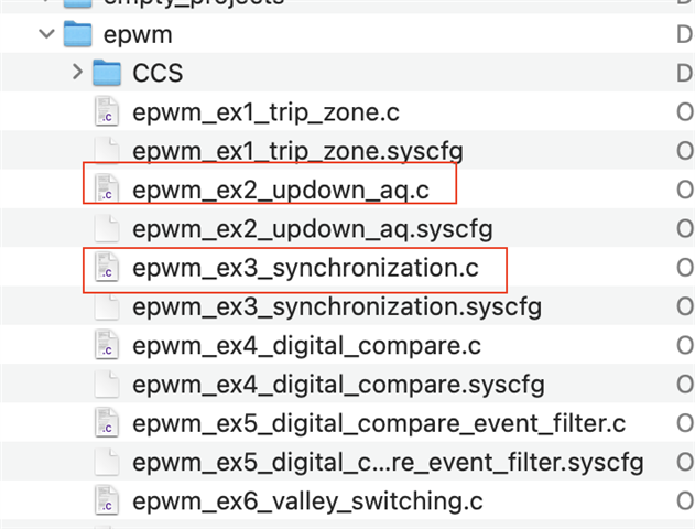
    I will recommend you to first get familiar with ePWM and check it meets your requirements. There are multiple examples in C2000Ware SDK DriverLib examples.  

    C:/ti/c2000/C2000Ware_4_02_00_00/driverlib/f28004x/examples/epwm/CCS

    Please go through C2000 Academy to learn about ePWM and then you can try ePWM lab exercise.

    I will close this thread now as your initial issue is resolved. If you have any specific ePWM issue, please create new thread.

    Regards, Santosh