This thread has been locked.

If you have a related question, please click the "Ask a related question" button in the top right corner. The newly created question will be automatically linked to this question.

TMS320F28069F: The details of my issue are as follows

Part Number: TMS320F28069F
Other Parts Discussed in Thread: MOTORWARE

Hi team,

Currently I'm using the motorware_1_01_00_14 version. The following problems have emerged in the project: (the latest version is motorware_1_01_00_18)

1) The rated power is 5KW, the bus voltage is 72V, the maximum peak current is 150A (using InstaSPINTm-FOC), and two current sensors are used. The problem now is that it cannot rotate when I start it. Most of them can start smoothly without load but they cannot start smoothly when they are loaded. Very rarely, they run smoothly after being loaded. Could you please analyze my issue?
2) The latest version is motorware_1_01_00_18, what is the difference between it and the motorware_1_01_00_14 that we are currently using?
3) For different power motors, we mainly modify the following parameters. Do I need to modify other parameters?

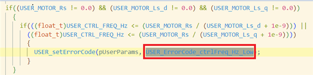
4) The motor is 20V/20W, the stator resistance is 9Ω, the inductance is 45uH, 1 pair of stages, 30,000 revolutions, the reverse electromotive force cannot be identified, and the control frequency is too low. As the frequency in the algorithm is greater than the resistance divided by the inductance and the inductance of the motor is too small, the required frequency is too high.

Kind regards,

Katherine

  • Most of them can start smoothly without load but they cannot start smoothly when they are loaded. Very rarely, they run smoothly after being loaded. Could you please analyze my issue?

    What load is adding when start the motor? A very heavy load? Full load? What's the percent of the added load vs. the rated load of the motor?

    What current sensor are you using? Shunt resistor on low-side, or on motor lines? Or hall-effect current sensor?

    Did you try to use the board to identify the motor and use the identified parameters to run the motor?

    Having an incorrect Rs value (especially a value higher than the actual Rs) will make the start-up behave poorly. You might refer to chapter 14 "Managing Full Load at Startup, Low-Speed and Speed Reversal" in InstaSPIN-FOC and InstaSPIN-MOTION User's Guide

    https://www.ti.com/lit/spruhj1

    1. Enable stator Rs recalibration before startup
    2. Enable forced angle
    3. Make sure that the current ADC offset is calibrated
    2) The latest version is motorware_1_01_00_18, what is the difference between it and the motorware_1_01_00_14 that we are currently using?

    The same FAST library in ROM. Just a little bit changes on SVGEN and PWM modules, you may have a look at the InstaSPIN lab user's guide for the detailed changes between different versions.

    4) The motor is 20V/20W,

    What do you mean this? Is a different motor? What board is using for this motor? You should design the right voltage & current sensing circuit for this motor to improve the sampling resolution, not use the same hardware board for this small motor.

  • Hi Yanming,

    The hardware circuit can improve the resolution of the voltage and current, but how could I eliminate the false alarm of the software? The ratio of the stator resistance to the inductance is too large.

    The load is not heavy, 20% of the rated load, and the Hall current sensor is used to collect the two-phase current.

    Regards,

    Katherine

  • The hardware circuit can improve the resolution of the voltage and current, but how could I eliminate the false alarm of the software?

    What's the false alarm of the software?

    the Hall current sensor is used to collect the two-phase current.

    Any signals delay on Hall current sensor? And is there any filter on current signals?

  • Hi Yanming,

    1. The error that the control frequency is too low:

    USER_ErrorCode_ctrlFreq_Hz_Low

    2. The Hall current sensor has a delay of several us, and the filter is a small capacitor.

    3. In addition, USER_CTRL_FREQ_HZ=9/45 * 1000000, which is 200KHz, can it be so large here?

    4. The added signal conditioning circuit looks like this:

    1) V_1_P is the network label of the voltage signal output by the Hall current sensor.

    2) The capacitor C7 of the filter has a capacitance value of 10nF.

  • 3. In addition, USER_CTRL_FREQ_HZ=9/45 * 1000000, which is 200KHz, can it be so large here?

    Seems like the motor parameters are not correct. The Rs is too high and the Ls is too low. Check the motor datasheet to make sure that these values are correct.

    2. The Hall current sensor has a delay of several us, and the filter is a small capacitor.

    The delay is too large to run a high speed motor, low power motor.

    2) The capacitor C7 of the filter has a capacitance value of 10nF.

    The capacitor could be changed to 1~2.2nF. And the hall sensor is suitable for a high current motor, not the low power low current motor.