This thread has been locked.

If you have a related question, please click the "Ask a related question" button in the top right corner. The newly created question will be automatically linked to this question.

LAUNCHXL-F280049C: PhaseShift ePWM(4A/B, 5A/B)

Part Number: LAUNCHXL-F280049C
Other Parts Discussed in Thread: C2000WARE

Hello, TI Experts,

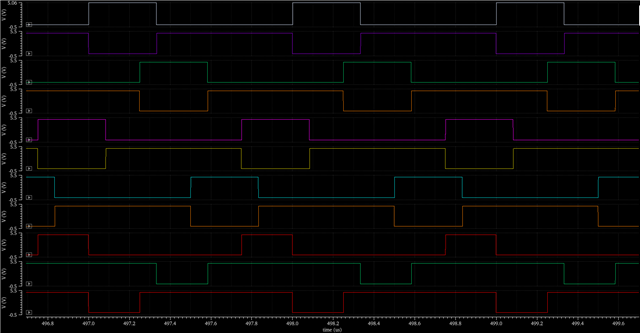
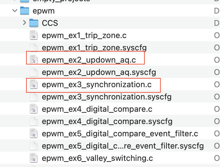
In my application, I guess I likely need 6 or 7 ePWM(A/B) pairs[see my attached PWM output waveforms]. I'm trying to figure out whether I can realize this from LAUNCHXL-F280049C LAUNCHPAD. Therefore, I'm planning to combine epwm_ex2_updown_aq.c and epwm_ex3_synchronization.c(if needed) from C:/ti/c2000/C2000Ware_4_02_00_00/driverlib/f28004x/examples/epwm/CCS. 
Questions: 

1. Can I generate the simulated PWM outputs with this Launchpad with ePWM1,2,3,4,5,6,8 (i dont see ePWM7)? 
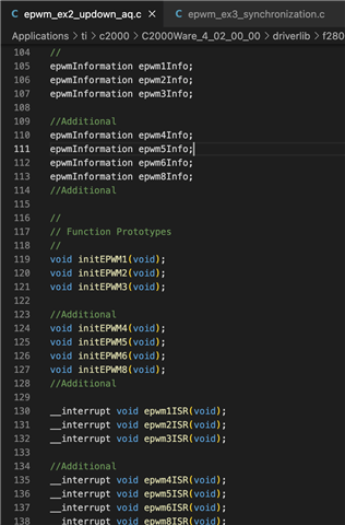
2. In epwm_ex2_updown_aq.c default program, do EPWM1A and EPWM1B naturally complementary like it's in PWM waveform inverter picture? If not, how to make them 180 deg phase shifts.

3. I'm planning to activate EPWM4,5,6,8 in epwm_ex2_upddown_aq.c by adding[

epwmInformation epwm_XInfo;
void initEPWM_X(void);
__interrupt void epwm_XISR(void);
etc....]

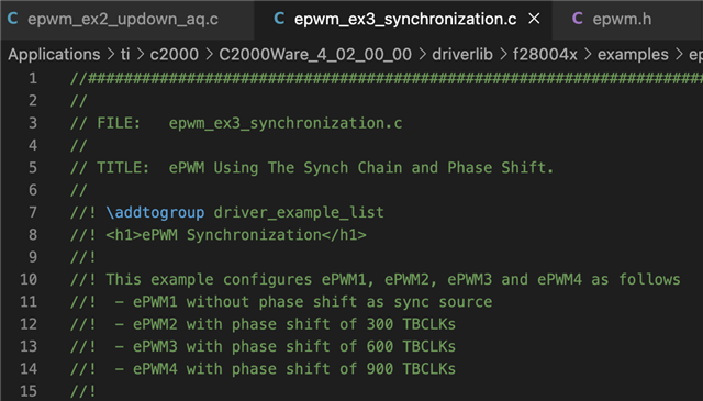
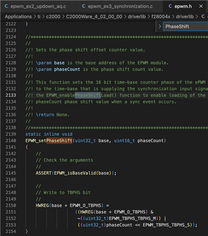
(correct me if i'm wrong) it looks like the EPWM1,2,3,4 are 90 deg phase shift in order per comments from epwm_ex3_syn. Does it mean the EPWM5 has the same phase with EPWM1, EPWM6 has the same phase with EPWM2, AND EPWM8 has the same phase with EPWM4? If so, then, I might need to adjust the phase shift values for EPWM5,6,8. Sounds like we have to modify the EPWM_setPhaseShfit () function or define phasecount value, but I'm not sure how to do it? Any comments will be very helpful!


  • 1. Can I generate the simulated PWM outputs with this Launchpad with ePWM1,2,3,4,5,6,8 (i dont see ePWM7)? 
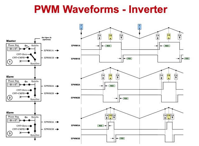
    Yes! Each ePWM can be configured however you want.

    2. In epwm_ex2_updown_aq.c default program, do EPWM1A and EPWM1B naturally complementary like it's in PWM waveform inverter picture? If not, how to make them 180 deg phase shifts. Does it mean the EPWM5 has the same phase with EPWM1, EPWM6 has the same phase with EPWM2, AND EPWM8 has the same phase with EPWM4? If so, then, I might need to adjust the phase shift values for EPWM5,6,8. Sounds like we have to modify the EPWM_setPhaseShfit () function or define phasecount value, but I'm not sure how to do it?

    In ex2, we adjust the CMP values within those interrupt handlers to change the duty cycle.

    In order to achieve a certain phase shift you can do the following:

    This is the formula to calculate the desired phase shift. taken from this great resource! 

    1. First enable phase shift with this driverlib function

    EPWM_enablePhaseShiftLoad(myEPWM0_BASE);
    2. Then set the phase shift value 
    EPWM_setPhaseShift(myEPWM0_BASE, 180);
    If you have not checked out SysConfig Tool, I would highly recommend giving it a try. This tool will help a lot with initializing your epwm and it has a great ui to visualize what code is being generated.
    Hope this helps!
    Best Regards,
    Ryan Ma
  • Hello, Ryan,

    Thanks for the quick reply! I got the ideas(Still trying to figure it out...). In the meanwhile, I have two questions:

    1. In the epwm_ex2_updown_aq, I would like to see whether the fsw(1/pwm period) can boost 10 times to 250kHz. So, I changed #define EPWM1_TIMER_TBPRD 200U  (from 2000U to 200U), but the switching freq is still the 25kHz. I'm not sure what's wrong. which drivelib's XXX.h file and which functions determine the switching freq? what are the right functions to add in epwm_ex2_updown_aq? 

    2. for the epwm_ex3_synchoronization, i cannot tell what type it is. Is it count-up? count-down? or count-up&down?

    Thanks!

  • Hello Hua,

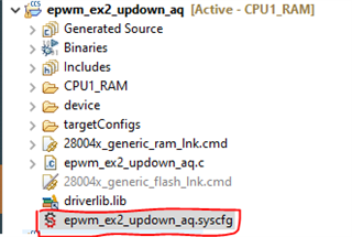
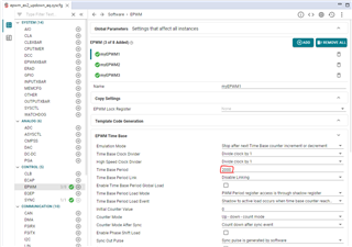
    1. I assume you changed the macro definition within the .c file. The macro being used in that file is only for the header to let you know that the period is set to 2000. In order to actually change the period you need to open the SysCfg file in the project folder.

    a. Double click on this .syscfg file

    b. You can see within SysCfg the time base period is 2000. Here is where you can change to 200.

    c. Save this file, and rebuild your project and you should see a change in the frequency.

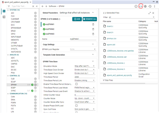
    Note: The code that gets generated from syscfg can be found by clicking this icon and you can see real updates whenver you change any configuration within SysCfg.

    2. All epwms are in up count mode.

    Best,

    Ryan Ma

  • I'm able to get 180 deg phase shift now. This resolved my issue. One last quick thing before we close this. 

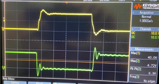
    I used epwm_ex3 up-count mode to generate epwm1A/1B like the attached pictures with 25% duty and 1MHz fsw. I found there are rising-edge and falling edge ringings occurs likely due to signal corruption or glitch. Are there any quick ways i could remove or minizine them? can I try enable event trigger, will that helps? 

    Best Regards,