Hi,
I am trying to use 3 launchpads- 1 master and 2 slaves and I would like to use the master to synchronize EPWM output on both the slaves.
I am using 2 signals to achieve this synchronization, my output sinewave is 18kHz.
1. EXTSYNC1 from XBAR5 with a 90kHz signal from Master
2. 1Hz signal from Master to reset index of the SPWM samples array of size 10.
I was initially using EPWM interrupt to compute CMPA register values and update it in the CMPA register,
but due to some other issues I had to switch to using DMA interrupt for updating the CMPA register
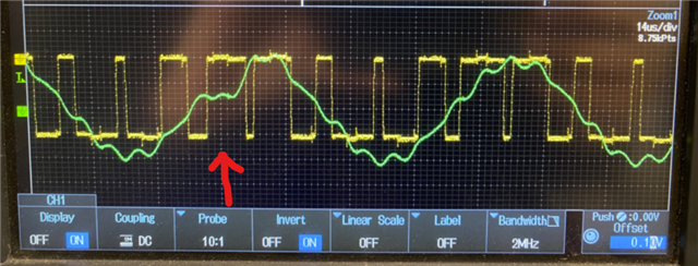
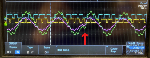
Once the DMA has been introduced, my sine output shape is being affected due to EXTSYNC1.
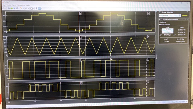
In other words, when I have EPWM_enablePhaseShiftLoad(EPWM1_BASE); line in the code, which uses EXTSYNC1 to load TBPHS (Phase Count = 0) into TBCTR. My sine wave output is distorted as shown below
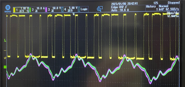
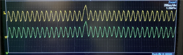
My ideal output looks like below

Please find my EPWM initialization below
void EPWM_1_Initialization(void)
{
    /* Disable TBCLK within the EPWM*/
    SysCtl_disablePeripheral(SYSCTL_PERIPH_CLK_TBCLKSYNC);

    /* Time Base Control Register */
    EPWM_setTimeBaseCounterMode(EPWM1_BASE, EPWM_COUNTER_MODE_UP_DOWN);

    EPWM_setSyncOutPulseMode(EPWM1_BASE, EPWM_SYNC_OUT_PULSE_ON_COUNTER_ZERO);

    EPWM_setPeriodLoadMode(EPWM1_BASE, EPWM_PERIOD_SHADOW_LOAD);
    EPWM_selectPeriodLoadEvent(EPWM1_BASE, EPWM_SHADOW_LOAD_MODE_COUNTER_ZERO);

    EPWM_enablePhaseShiftLoad(EPWM1_BASE);

    EPWM_setCountModeAfterSync(EPWM1_BASE, EPWM_COUNT_MODE_DOWN_AFTER_SYNC);
    EPWM_setClockPrescaler(EPWM1_BASE, EPWM_CLOCK_DIVIDER_1,
                            EPWM_HSCLOCK_DIVIDER_1);

    /* Setup Time-Base (TB) Submodule --*/
    EPWM_setTimeBasePeriod(EPWM1_BASE, EPWM1_TIME_PERIOD);

    /* Time-Base Phase Register */
    EPWM_setPhaseShift(EPWM1_BASE, 0);

    /* Time Base Counter Register */
    EPWM_setTimeBaseCounter(EPWM1_BASE, 0);

    /* Setup Counter_Compare (CC) Submodule */
    /* Counter Compare Control Register */
    EPWM_setCounterCompareShadowLoadMode(EPWM1_BASE, EPWM_COUNTER_COMPARE_A,
                                            EPWM_COMP_LOAD_ON_CNTR_ZERO_PERIOD);
    EPWM_setCounterCompareShadowLoadMode(EPWM1_BASE, EPWM_COUNTER_COMPARE_B,
                                            EPWM_COMP_LOAD_ON_CNTR_ZERO);
    EPWM_setCounterCompareShadowLoadMode(EPWM1_BASE, EPWM_COUNTER_COMPARE_C,
                                            EPWM_COMP_LOAD_ON_CNTR_ZERO);
    EPWM_setCounterCompareShadowLoadMode(EPWM1_BASE, EPWM_COUNTER_COMPARE_D,
                                            EPWM_COMP_LOAD_ON_CNTR_ZERO);

    EPWM_setCounterCompareValue(EPWM1_BASE, EPWM_COUNTER_COMPARE_A, 0);
    EPWM_setCounterCompareValue(EPWM1_BASE, EPWM_COUNTER_COMPARE_B, 139);
    EPWM_setCounterCompareValue(EPWM1_BASE, EPWM_COUNTER_COMPARE_C, 32000);
    EPWM_setCounterCompareValue(EPWM1_BASE, EPWM_COUNTER_COMPARE_D, 32000);

    /* Setup Action-Qualifier (AQ) Submodule */
    EPWM_setActionQualifierAction(EPWM1_BASE, EPWM_AQ_OUTPUT_A,
                                    EPWM_AQ_OUTPUT_HIGH,
                                    EPWM_AQ_OUTPUT_ON_TIMEBASE_DOWN_CMPA);
    EPWM_setActionQualifierAction(EPWM1_BASE, EPWM_AQ_OUTPUT_A,
                                    EPWM_AQ_OUTPUT_LOW,
                                    EPWM_AQ_OUTPUT_ON_TIMEBASE_UP_CMPA);
    EPWM_setActionQualifierAction(EPWM1_BASE, EPWM_AQ_OUTPUT_B,
                                    EPWM_AQ_OUTPUT_LOW,
                                    EPWM_AQ_OUTPUT_ON_TIMEBASE_DOWN_CMPA);
    EPWM_setActionQualifierAction(EPWM1_BASE, EPWM_AQ_OUTPUT_B,
                                    EPWM_AQ_OUTPUT_HIGH,
                                    EPWM_AQ_OUTPUT_ON_TIMEBASE_UP_CMPA);

    /* Action Qualifier Software Force Register */
    EPWM_setActionQualifierContSWForceShadowMode(
            EPWM1_BASE, EPWM_AQ_SW_SH_LOAD_ON_CNTR_ZERO);

    /* Action Qualifier Continuous S/W Force Register */
    EPWM_setActionQualifierContSWForceAction(EPWM1_BASE, EPWM_AQ_OUTPUT_A,
                                                EPWM_AQ_SW_DISABLED);
    EPWM_setActionQualifierContSWForceAction(EPWM1_BASE, EPWM_AQ_OUTPUT_B,
                                                EPWM_AQ_SW_DISABLED);

    /* Setup Dead-Band Generator (DB) Submodule */
    /*  Dead-Band Generator Control Register */
    EPWM_setRisingEdgeDeadBandDelayInput(EPWM1_BASE, EPWM_DB_INPUT_EPWMA);
    EPWM_setFallingEdgeDeadBandDelayInput(EPWM1_BASE, EPWM_DB_INPUT_EPWMA);

    EPWM_setDeadBandDelayPolarity(EPWM1_BASE, EPWM_DB_RED,
                                    EPWM_DB_POLARITY_ACTIVE_HIGH);
    EPWM_setDeadBandDelayPolarity(EPWM1_BASE, EPWM_DB_FED,
                                    EPWM_DB_POLARITY_ACTIVE_LOW);

    EPWM_setDeadBandDelayMode(EPWM1_BASE, EPWM_DB_RED, true);
    EPWM_setDeadBandDelayMode(EPWM1_BASE, EPWM_DB_FED, true);

    EPWM_setRisingEdgeDelayCountShadowLoadMode(EPWM1_BASE,
                                                EPWM_RED_LOAD_ON_CNTR_ZERO);
    EPWM_setFallingEdgeDelayCountShadowLoadMode(EPWM1_BASE,
                                                EPWM_FED_LOAD_ON_CNTR_ZERO);

    EPWM_setFallingEdgeDelayCount(EPWM1_BASE, 40);
    EPWM_setRisingEdgeDelayCount(EPWM1_BASE, 40);

    /* Setup Event-Trigger (ET) Submodule */
    /* Event Trigger Selection and Pre-Scale Register */
    EPWM_enableADCTrigger(EPWM1_BASE, EPWM_SOC_A);
    EPWM_setADCTriggerSource(EPWM1_BASE, EPWM_SOC_A,
                                EPWM_SOC_TBCTR_ZERO_OR_PERIOD);
    EPWM_setADCTriggerEventPrescale(EPWM1_BASE, EPWM_SOC_A, 1);
    EPWM_disableADCTrigger(EPWM1_BASE, EPWM_SOC_B);
    EPWM_setADCTriggerSource(EPWM1_BASE, EPWM_SOC_B,
                                EPWM_SOC_TBCTR_ZERO_OR_PERIOD);
    EPWM_setADCTriggerEventPrescale(EPWM1_BASE, EPWM_SOC_B, 1);

    EPWM_enableInterrupt(EPWM1_BASE);
    EPWM_setInterruptSource(EPWM1_BASE, EPWM_INT_TBCTR_ZERO_OR_PERIOD);
    EPWM_setInterruptEventCount(EPWM1_BASE, 1);

    /* Setup PWM-Chopper (PC) Submodule */
    /* PWM Chopper Control Register */
    EPWM_disableChopper(EPWM1_BASE);
    EPWM_setChopperFreq(EPWM1_BASE, 0);
    EPWM_setChopperFirstPulseWidth(EPWM1_BASE, 0);
    EPWM_setChopperDutyCycle(EPWM1_BASE, 0);

    /* Set up Trip-Zone (TZ) Submodule */
    EPWM_disableTripZoneSignals(EPWM1_BASE, EPWM_TZ_SIGNAL_CBC1);
    EPWM_disableTripZoneSignals(EPWM1_BASE, EPWM_TZ_SIGNAL_CBC2);
    EPWM_disableTripZoneSignals(EPWM1_BASE, EPWM_TZ_SIGNAL_CBC3);
    EPWM_disableTripZoneSignals(EPWM1_BASE, EPWM_TZ_SIGNAL_CBC4);
    EPWM_disableTripZoneSignals(EPWM1_BASE, EPWM_TZ_SIGNAL_CBC5);
    EPWM_disableTripZoneSignals(EPWM1_BASE, EPWM_TZ_SIGNAL_CBC6);
    EPWM_disableTripZoneSignals(EPWM1_BASE, EPWM_TZ_SIGNAL_DCAEVT2);
    EPWM_disableTripZoneSignals(EPWM1_BASE, EPWM_TZ_SIGNAL_DCBEVT2);
    EPWM_disableTripZoneSignals(EPWM1_BASE, EPWM_TZ_SIGNAL_OSHT1);
    EPWM_disableTripZoneSignals(EPWM1_BASE, EPWM_TZ_SIGNAL_OSHT2);
    EPWM_disableTripZoneSignals(EPWM1_BASE, EPWM_TZ_SIGNAL_OSHT3);
    EPWM_disableTripZoneSignals(EPWM1_BASE, EPWM_TZ_SIGNAL_OSHT4);
    EPWM_disableTripZoneSignals(EPWM1_BASE, EPWM_TZ_SIGNAL_OSHT5);
    EPWM_disableTripZoneSignals(EPWM1_BASE, EPWM_TZ_SIGNAL_OSHT6);

    EPWM_enableTripZoneSignals(EPWM1_BASE, EPWM_TZ_SIGNAL_DCAEVT1);
    EPWM_enableTripZoneSignals(EPWM1_BASE, EPWM_TZ_SIGNAL_DCBEVT1);

    /* Trip Zone Control Register */
    EPWM_setTripZoneAction(EPWM1_BASE, EPWM_TZ_ACTION_EVENT_TZA,
                            EPWM_TZ_ACTION_LOW);
    EPWM_setTripZoneAction(EPWM1_BASE, EPWM_TZ_ACTION_EVENT_TZB,
                            EPWM_TZ_ACTION_LOW);

    EPWM_setTripZoneAction(EPWM1_BASE, EPWM_TZ_ACTION_EVENT_DCAEVT1,
                            EPWM_TZ_ACTION_DISABLE);
    EPWM_setTripZoneAction(EPWM1_BASE, EPWM_TZ_ACTION_EVENT_DCAEVT2,
                            EPWM_TZ_ACTION_DISABLE);
    EPWM_setTripZoneAction(EPWM1_BASE, EPWM_TZ_ACTION_EVENT_DCBEVT1,
                            EPWM_TZ_ACTION_DISABLE);
    EPWM_setTripZoneAction(EPWM1_BASE, EPWM_TZ_ACTION_EVENT_DCBEVT2,
                            EPWM_TZ_ACTION_DISABLE);

    /* Trip Zone Enable Interrupt Register */
    EPWM_enableTripZoneInterrupt(EPWM1_BASE, EPWM_TZ_INTERRUPT_OST);
    EPWM_enableTripZoneInterrupt(EPWM1_BASE, EPWM_TZ_INTERRUPT_CBC);
    EPWM_enableTripZoneInterrupt(EPWM1_BASE, EPWM_TZ_INTERRUPT_DCAEVT1);
    EPWM_enableTripZoneInterrupt(EPWM1_BASE, EPWM_TZ_INTERRUPT_DCAEVT2);
    EPWM_enableTripZoneInterrupt(EPWM1_BASE, EPWM_TZ_INTERRUPT_DCBEVT1);
    EPWM_enableTripZoneInterrupt(EPWM1_BASE, EPWM_TZ_INTERRUPT_DCBEVT2);

    /* Digital Compare A Control Register */
    EPWM_disableDigitalCompareSyncEvent(EPWM1_BASE, EPWM_DC_MODULE_A);
    EPWM_enableDigitalCompareADCTrigger(EPWM1_BASE, EPWM_DC_MODULE_A);
    EPWM_setDigitalCompareEventSyncMode(EPWM1_BASE, EPWM_DC_MODULE_A,
                                        EPWM_DC_EVENT_1,
                                        EPWM_DC_EVENT_INPUT_SYNCED);
    EPWM_setDigitalCompareEventSyncMode(EPWM1_BASE, EPWM_DC_MODULE_A,
                                        EPWM_DC_EVENT_2,
                                        EPWM_DC_EVENT_INPUT_NOT_SYNCED);

    /* Digital Compare B Control Register */
    EPWM_disableDigitalCompareSyncEvent(EPWM1_BASE, EPWM_DC_MODULE_B);
    EPWM_disableDigitalCompareADCTrigger(EPWM1_BASE, EPWM_DC_MODULE_B);
    EPWM_setDigitalCompareEventSyncMode(EPWM1_BASE, EPWM_DC_MODULE_B,
                                        EPWM_DC_EVENT_1,
                                        EPWM_DC_EVENT_INPUT_SYNCED);
    EPWM_setDigitalCompareEventSyncMode(EPWM1_BASE, EPWM_DC_MODULE_B,
                                        EPWM_DC_EVENT_2,
                                        EPWM_DC_EVENT_INPUT_SYNCED);

    /* Digital Compare Trip Select Register */
    EPWM_enableDigitalCompareTripCombinationInput(EPWM1_BASE,
    EPWM_DC_COMBINATIONAL_TRIPIN4,
                                                    EPWM_DC_TYPE_DCAH);
    EPWM_enableDigitalCompareTripCombinationInput(EPWM1_BASE,
    EPWM_DC_COMBINATIONAL_TRIPIN1,
                                                    EPWM_DC_TYPE_DCAL);
    EPWM_enableDigitalCompareTripCombinationInput(EPWM1_BASE,
    EPWM_DC_COMBINATIONAL_TRIPIN5,
                                                    EPWM_DC_TYPE_DCBH);
    EPWM_enableDigitalCompareTripCombinationInput(EPWM1_BASE,
    EPWM_DC_COMBINATIONAL_TRIPIN1,
                                                    EPWM_DC_TYPE_DCBL);

    /* Trip Zone Digital Comparator Select Register */
    EPWM_setTripZoneDigitalCompareEventCondition(EPWM1_BASE,
                                                    EPWM_TZ_DC_OUTPUT_A1,
                                                    EPWM_TZ_EVENT_DCXH_HIGH);
    EPWM_setTripZoneDigitalCompareEventCondition(EPWM1_BASE,
                                                    EPWM_TZ_DC_OUTPUT_A2,
                                                    EPWM_TZ_EVENT_DC_DISABLED);
    EPWM_setTripZoneDigitalCompareEventCondition(EPWM1_BASE,
                                                    EPWM_TZ_DC_OUTPUT_B1,
                                                    EPWM_TZ_EVENT_DCXH_HIGH);
    EPWM_setTripZoneDigitalCompareEventCondition(EPWM1_BASE,
                                                    EPWM_TZ_DC_OUTPUT_B2,
                                                    EPWM_TZ_EVENT_DC_DISABLED);

    /* Digital Compare Filter Control Register */
    EPWM_disableDigitalCompareBlankingWindow(EPWM1_BASE);
    EPWM_setDigitalCompareBlankingEvent(EPWM1_BASE,
                                        EPWM_DC_WINDOW_START_TBCTR_ZERO);
    EPWM_disableDigitalCompareWindowInverseMode(EPWM1_BASE);
    EPWM_setDigitalCompareFilterInput(EPWM1_BASE,
                                        EPWM_DC_WINDOW_SOURCE_DCAEVT1);

    EPWM_setDigitalCompareWindowOffset(EPWM1_BASE, 0);
    EPWM_setDigitalCompareWindowLength(EPWM1_BASE, 0);

    /* Digital Compare Capture Control Register */
    EPWM_disableDigitalCompareCounterCapture(EPWM1_BASE);

    /* HRPWM Configuration Register */
    HRPWM_setOutputSwapMode(EPWM1_BASE, FALSE);
    HRPWM_setChannelBOutputPath(EPWM1_BASE, HRPWM_OUTPUT_ON_B_NORMAL);

    /* Update the Link Registers with the link value for all the Compare values and TBPRD */
    /* No error is thrown if the ePWM register exists in the model or not */
    EPWM_setupEPWMLinks(EPWM1_BASE, EPWM_LINK_WITH_EPWM_1, EPWM_LINK_TBPRD);
    EPWM_setupEPWMLinks(EPWM1_BASE, EPWM_LINK_WITH_EPWM_1, EPWM_LINK_COMP_A);
    EPWM_setupEPWMLinks(EPWM1_BASE, EPWM_LINK_WITH_EPWM_1, EPWM_LINK_COMP_B);
    EPWM_setupEPWMLinks(EPWM1_BASE, EPWM_LINK_WITH_EPWM_1, EPWM_LINK_COMP_C);
    EPWM_setupEPWMLinks(EPWM1_BASE, EPWM_LINK_WITH_EPWM_1, EPWM_LINK_COMP_D);

    /* SYNCPER - Peripheral synchronization output event */
    HRPWM_setSyncPulseSource(EPWM1_BASE, HRPWM_PWMSYNC_SOURCE_PERIOD);

}
Question:
Is there any reason why EXTSYNC1 signal should impact SPWM when using DMA?
Regards,
Rashmitha