This thread has been locked.

If you have a related question, please click the "Ask a related question" button in the top right corner. The newly created question will be automatically linked to this question.

TMS320F2812: Clock interrupt error

Part Number: TMS320F2812

The TMS320F2812 we are using now, I use an external active crystal oscillator of 30M, PLL I set 2, frequency division 2, and the last system clock is 30M, but when the power is off and the chip is powered on, it runs normally, and after a period of time, I execute the action;

The function of the device itself will generate discharge pulse, so EMI interference will be generated. When the interference occurs, the operating clock of the chip seems to be changed. My timer setting is 10ms, and now it seems to be 20ms. I have a pin that periodically outputs a 1.5s cycle change signal. At this time, it also becomes a 3s cycle. At the same time, power off and reset can return to normal; The attachment is a schematic diagram. I want to know how to adjust the hardware so that it is not affected by EMI interference, or how to locate the point in the software that causes the timer interrupt error, so as to avoid it by software;

1881.pdf

  • Zhang,

    To clarify, you mention a power off and reset will return the device to normal.  Will just a reset(XRSn pin) correct the device behavior or does the power have to be cycled.

    Since the result is that your clock is 1/2 the expected setting, it looks like the PLL register has been reset back to its default state, which would give 15MHz CPU clock.  A toggle of XRSn or the watchdog timeout could cause this, but we would expect the device to boot back up and set the PLL again.

    Looking at the schematic, can you give some more details on the circuit that controls XRSn, as well as any more passives on the JTAG signals not shown in the diagram?

    Best,

    Matthew

  • JTAG We led the lead from the PCB board to the connector of the chassis. During the experiment, we found that when we received the interference, there would be a crash or reset, but the clock had never been changed. Later, in order not to crash or reset, we removed the lead from the connector to the PCB board, but the solder joint was closer to the connector, and there were other leads on the connector, After that, the clock was changed in the experiment.

    I use XDS100V2 
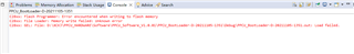
I am using XDS100V2, and the following error occurs

  • CAN YOU REPLY THE PROBLEM

  • Zhang,

    For the JTAG signals can you confirm if you have external pulldown on TRSTn and Pull up on EMU0/1.  It is very important to keep TRSTn from going high when the emulator pod is not plugged in.  If  there is not a good PD on this pin, it can change state which will take the device out of Test Reset.

    If you could share the portion of the schematic that shows this(as well as XRSn control) we can see if that may be the issue.

    Best,

    Matthew