This thread has been locked.

If you have a related question, please click the "Ask a related question" button in the top right corner. The newly created question will be automatically linked to this question.

TMS320F280025: Problem with CAN receive after power up

Part Number: TMS320F280025

I'm having a weird issue with CAN 0 on the F280025 (80 pin if it makes a difference).

If the processor is powered up normally (ie. 3.3V applied).  It seems to send CAN messages just fine, but cannot receive anything.  If I reset the processor (pulling XRSn low) then it works (or if I hold XRSn low during startup).  Everything else seems to work just fine (boots properly from flash, pwms work, adcs function, etc..).  When running off a debugger, I never have the issue (I would guess because it toggles the XRSn).

I'm using all the recommended practices for XRSn and 3.3 comes up very fast and is super stable. 

I can properly detect that I'm not receiving and trying to re-init the CAN0 and it doesn't help. Only pulling XRSn low works.  I've also tried using the simulated XRSn to reset the processor on startup... that didn't work either...  

I haven't had this issue on F280049 or other C2000 processors.  Any thoughts on how to fix this?

  • Hi Kyle,

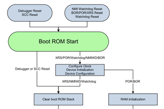
    This is probably a tart up issue and not at all related to CAN based on the behavior that you just described.  When not running off the debugger, can you scope the xRSN pin to see if there are periodic toggles?  Also please refer to below boot flow diagram snippet from the TRM:

    There is a different flow when started from debugger an and POR/xRSN reset/etc...  One of the first things to check is to see if watchdog is disabled if you are not using it or if you are, that it is serviced otherwise there would be periodic reset that you can observe on the XRSN pin.

    Regards,

    Joseph

  • I've scoped the XRSn pin versus the 3.3V, it follows with about 1ms delay, then is rock solid (no glitches).  

    I am using the watchdog (pretty long delay on it), but I can confirm that it's not triggering as all the other systems are up and running and I have a run time counter that is still counting up without resetting.  We'll try turning it off to see if makes a difference.  Let you know soon.

    We did find one other method of getting it to work... holding the XRSn pin low while powering up, then releasing (use of a button).  Tried making the pull up resistor larger to slow down the bring up of this pin, but it still resulted in the CAN receive issue.  

  • Hi Kyle,

    Any further findings with the WD being turned off?  By the way in your start up flow, did you ensure that CAN initialization is one of the first routines to be performed?  Maybe code is branching off earlier and bypassed CAN initialization routines.

    Regards,

    Joseph

  • Tried WD off... no help.  Same behavior..

    CAN is being initialized... Again, I am seeing transmissions from the board, just not receiving anything.  Plus, if it hasn't received anything for 4 seconds it forces a re-init.

    I thought maybe since CAN timing is pretty precise, it might be the crystal is not calibrating accurately enough for CAN to work properly.  That wasn't it either.

    I used a 200kHz PWM to see if the timing is any different.  It's not.

    I tried the internal oscillatorjust to see and it's 200kHz timing showed up as 202.5kHz, which is expected to not be perfect.  But, CAN had the same behavior.  Wouldn't work without manually pressing the reset button on the board... It did work even with the timing being off too.

    This is the init function.  It's basically the same as the examples...

    void Comms_SetupCAN0(void)
    {
        uint16_t i;
        //Setup the Pins:
        GPIO_SetupPinMux(CAN_0_RX_GPIO, GPIO_MUX_CPU1, CAN_0_RX_MUX);
        GPIO_SetupPinOptions(CAN_0_RX_GPIO, GPIO_INPUT, GPIO_ASYNC);
    
        GPIO_SetupPinMux(CAN_0_TX_GPIO, GPIO_MUX_CPU1, CAN_0_TX_MUX);
        GPIO_SetupPinOptions(CAN_0_TX_GPIO, GPIO_OUTPUT, GPIO_PUSHPULL);
    
        //
        // Initialize the CAN controllers
        //
        CAN_initModule(CAN_0_BASE);
    
        //
        // Set up the CAN bus bit rate to 250kHz for each module
        // Refer to the Driver Library User Guide for information on how to set
        // tighter timing control. Additionally, consult the device data sheet
        // for more information about the CAN module clocking.
        //
        //CHECK Bit timining value for this CAN speed
        CAN_setBitRate(CAN_0_BASE, DEVICE_CLOCK_SPEED, CAN_0_SPEED, 20);
    
        //
        // Enable interrupts on the CAN A peripheral.
        //
        //TCHECK and use proper interrupts
        //CAN_enableInterrupt(CAN_int_BASE, CAN_INT_IE0 | CAN_INT_ERROR | CAN_INT_STATUS);
        HWREG_BP(CAN_0_BASE + CAN_O_CTL) |= CAN_INT_IE0;// | CAN_INT_ERROR; //| CAN_INT_STATUS;
        //
        // Enable CAN test mode with external loopback
        //
        //CAN_enableTestMode(CAN_int_BASE, CAN_TEST_EXL);
    
         //
        // Interrupts that are used in this example are re-mapped to
        // ISR functions found within this file.
        // This registers the interrupt handler in PIE vector table.
        //
        //
        // Enable the CANinterrupt on the processor (PIE).
        //
        EALLOW;
        CAN_0_INTERRUPT_LOCATION = Coms_Can0ExternalInterrupt;
        CAN_0_INTERRUPT_ENABLE;
    
        EDIS;
        //
        // Enable the CAN-A interrupt signal
        //
        CAN_enableGlobalInterrupt(CAN_0_BASE, CAN_GLOBAL_INT_CANINT0);
    
        //Setup Mailbox:
        //Setup the mail boxes:
        //Setup the standard boxes for standard messages, accept all:
        for(i = FIRST_MAILBOX_FOR_STANDARD_MESSAGES; i < FIRST_MAILBOX_FOR_EXTENDED_MESSAGES; i++ )
        {
            //Accept all standard messages:
            // Message Object Parameters:
                //      CAN Module: A
                //      Message Object ID Number: 1
                //      Message Identifier: 0x1FFFFFFF
                //      Message Frame: Std
                //      Message Type: Receive
                //      Message ID Mask: 0x00000000 //No bits are used to reject messages
                //      Message Object Flags: UMask, MXtd, MDir
                //      Message Object flag CAN_MSG_OBJ_USE_ID_FILTER enables usage
                //       of msgIDMask parameter for Message Identifier based filtering
                //      Message Data Length: 0  //Don't care
            CAN_setupMessageObject(CAN_0_BASE, i,
                                   0x1FFFFFFF,
                                   CAN_MSG_FRAME_STD,
                                   CAN_MSG_OBJ_TYPE_RX,
                                   0x0,
                                   (CAN_MSG_OBJ_USE_ID_FILTER | CAN_MSG_OBJ_NO_FLAGS | CAN_MSG_OBJ_RX_INT_ENABLE),
                                   0);
        }
    
        for(i = FIRST_MAILBOX_FOR_EXTENDED_MESSAGES; i <= LAST_MAILBOX_FOR_EXTENDED_MESSAGES; i++ )
        {
            //Accept all Extended messages:
            // Message Object Parameters:
            //      CAN Module: A
            //      Message Object ID Number: 1
            //      Message Identifier: 0x1FFFFFFF
            //      Message Frame: Extended
            //      Message Type: Receive
            //      Message ID Mask: 0x00000000 //No bits are used to reject messages
            //      Message Object Flags: UMask, MXtd, MDir
            //      Message Object flag CAN_MSG_OBJ_USE_ID_FILTER enables usage
            //       of msgIDMask parameter for Message Identifier based filtering
            //      Message Data Length: "Don't care" for a Receive mailbox
            CAN_setupMessageObject(CAN_0_BASE, i,
                                       0x1FFFFFFF,
                                       CAN_MSG_FRAME_EXT,
                                       CAN_MSG_OBJ_TYPE_RX,
                                       0,
                                       (CAN_MSG_OBJ_USE_ID_FILTER | CAN_MSG_OBJ_NO_FLAGS | CAN_MSG_OBJ_RX_INT_ENABLE),
                                       0);
        }
    
        //
        // Start CAN module A operations
        //
        CAN_startModule(CAN_0_BASE);
    
        //Flush the Outgoing CAN Buffer:
        CAN_fifo_init(&Outgoing_CAN0);
    
        for(i = 0; i < (NUMBER_OF_TRANSMIT_MAILBOXES); i++ )
        {
    
            Can0MailBoxTransmittingStatus[i] = false;
        }
    }

  • Just wanted to have some clarification on the statement: "I am seeing transmissions from the board, just not receiving anything".  In the CAN initialization setup, all the message objects are defined as CAN_MSG_OBJ_TYPE_RX so with this I am assuming that CAN is only configured to receive CAN frames and and it is not set to transmit frames.  When you say that you are seeing transmissions from the board, was this observed on the TX line?  This is probably the CAN sending back some error frames to the CAN bus.

    It would be good to poke at the value of the CAN_ES register to see what the errors are but would be tricky since issue only happens without the debugger and you would need the debugger to view register values, but this might work:  Do not connect the debugger and power up your board and once you gave enough time for the code to run, connect the debugger and the target to Code Composer then using the registers view, look at contents of error register CAN_ES and interrupt pending register CAN_IPEN_21 to see if there are errors or any pending interrupt that may be waiting to be serviced and might be causing an overflow.

  • Joseph,

     "I am seeing transmissions from the board, just not receiving anything" -  This means other devices on the CAN network are seeing messages from this board. (I'll go a bit further and say complete messages, for instance it's sending an entire message giving the voltage of component A.  Not Error frames)  The TI chip for whatever reason seems to be correctly "Ack"ing the messages from the other devices, but is not actually seeing the messges (RX interrupt not firing?), unless the processor has been manually reset.

    "all the message objects are defined as CAN_MSG_OBJ_TYPE_RX so with this I am assuming that CAN is only configured to receive CAN frames"

    This is not true.  I setup some mailboxes for Extended pId receive and some for standard pid receive.  I reserve 3 boxes for transmit.  

    I've tried to connect after the startup...  Do you have a decent guide on that? I've seen various ways in the forums with varying degrees of success.  Usually, my processor restarts when connecting. 

    What I can try is just exporting the CAN_ES register to a transmit message, since I'm getting those, and see if anything weird is happening.

  • Kyle,

    Ok, understood.  Yes, it would be good if you can transmit CAN_ES contents as well as CAN_IPEN_21 regs just to see if there are pending interrupts.  On the debugger reconnection, first remove the gel file from the target configuration.  Gel file usually has commands to restart the processor if it detects connection.  This is done going to "Tools" (5th ribbon on the top menu) and choosing Gel Files.  There will be a window that will pop up and will display the gel file.  Right click on the gel file and choose "Remove".  This will temporarily remove the gel file in the loaded target configuration as long as you do not quit CCS or reload the target.  If you reload the target config, gel file would still be there.  You could then reconnect the target without the gel file once you do a POR on the board.

    Regards,

    Joseph